Speedhut 2-1_16 inch & 2-5_8 inch EGT or Cylinder Head Temp Gauge User Manual
Speedhut For the car
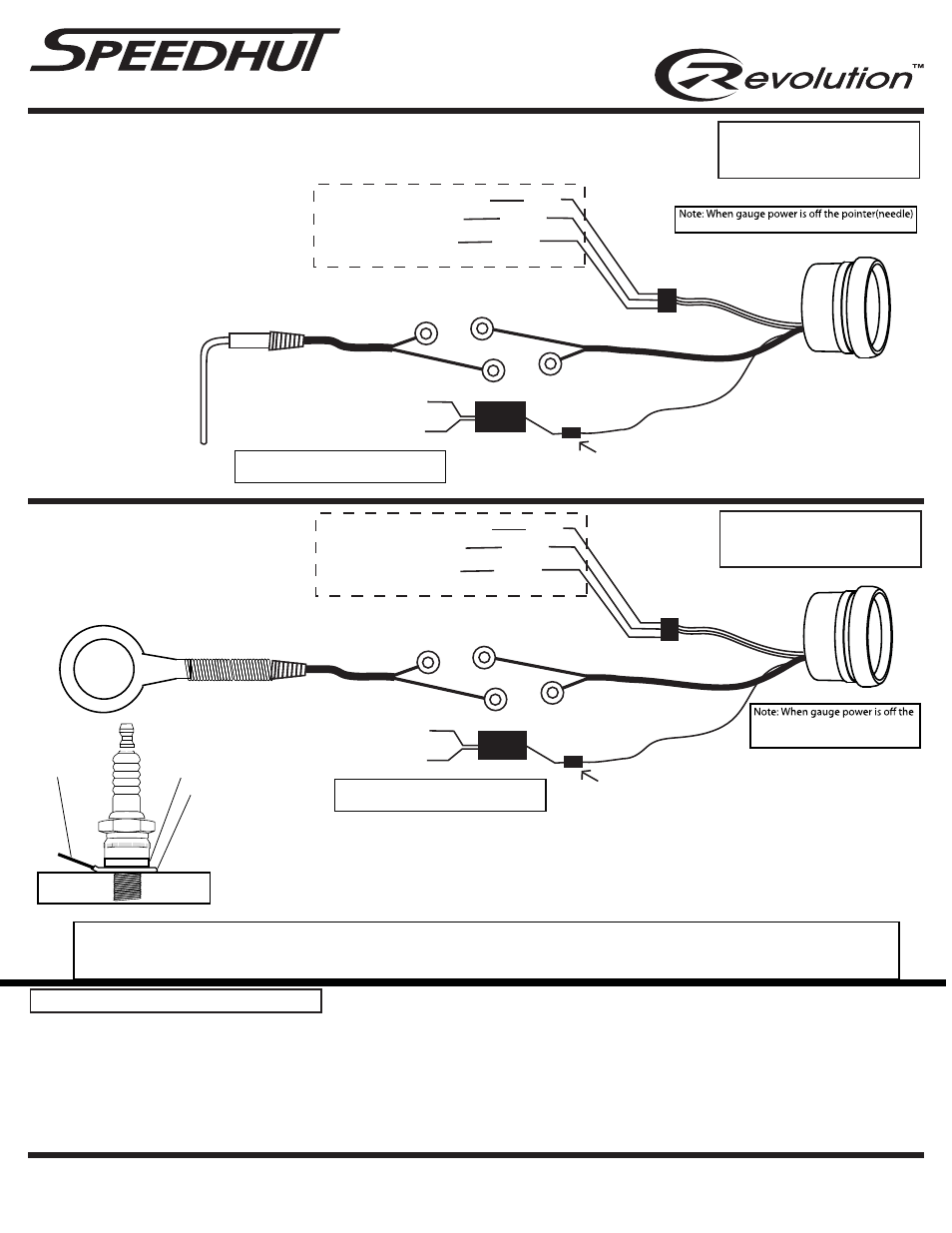
Ground (black)
+12 volts Dash lighting (white)
snap connector for dial lighting
1. Disconnect negative (-) Battery Cable
2. Connect wiring as above.
3. Mount Gauge for easy viewing. Use spin lock ring (included) to mount to panel. Spin ring
threads in both directions (depending on your dash panel thickness). Snap Gauge connector to wiring connector
4. Reconnect negative (-) battery cable.
Installation procedure
Type K thermocouple probe mounting steps.
1. Drill 1/4" hole into exhaust manifold at
desired EGT reading temp location. If mounting
probe before turbo inlet make sure NO metal
shavings can enter turbo inlet or damage can
occur to turbo.
2. Position weld fitting over hole
and 360 degree weld around
fitting to manifold.
3. insert probe into manifold
through weld fitting and tighten
using included compression
fitting.
+12 volts keyed ignition
(Red)
(Black)
Ground
(White)
+12 volts Dash lighting
2-1/16” and 2-5/8” and EGT/Cylinder Head Temp. Gauge Instructions
WARRANTY - Speedhut inc. warrants to the consumer for a period of 5 years from the date of purchase that the product will be free from defects in materials or workmanship.
Speedhut warrants to the consumer for a "LIFE-TIME" that the gauge circuit board will be free from defects in materials or workmanship. Please contact Speedhut service dept.
If you have a problem with this gauge. [email protected]
(Main gauge power)
(Pointer (needle) lighting)
(Gauge Dial lighting)
INVERTER IS REQUIRED FOR GAUGE DIAL LIGHTING
INVERTER
Note: Tie both lighting white wires together
and both black ground wires together.
+12 volts keyed ignition
(Red)
(Black)
Ground
(White)
+12 volts Dash lighting
(Main gauge power)
(Pointer (needle) lighting)
snap connector for dial lighting
Note: Tie both lighting white wires together
and both black ground wires together.
INVERTER
INVERTER IS REQUIRED FOR GAUGE DIAL LIGHTING
Ground (b ck)
+12 olts Dash lighting (white)
(Gauge Dial lighting)
la
v
NOTE: Both the EGT probe and the CHT probe are not able to be modified (either lengthened or shortened) without affecting the
calibration and readings on the gauge. If there is excess left after routing the wire, please coil it up and wire tie it loosely under hood.
Cylinder-Head Temp. Probe
1. Remove Spark Plug.
2. Place Probe under spark plug. Make sure probe sits
flat on cylinder head. Re- install spark plug.
3. Proper position of probe should not interfere with any
other components.
4. Tighten spark plug to manufacturers specifications.
Probe
Spark Plug Crush Washer
To Gauge
Cylinder
Head
Inverter Note: E18-686-5CR is single gauge inverter to light single gauge.
C01-18N-2 & C11-18A01 are multiple gauge lighting inverters that can light
up to 6 - 8 gauges depending on inverter model.
will remain in last powered position.
pointer(needle) will remain in last
powered position.
Power Draw = 0.2 Amp
5 Amp Inline Fuse Recommended
for +12 Keyed Ignition
Power Draw = 0.2 Amp
5 Amp Inline Fuse Recommended
for +12 Keyed Ignition