Fig 5: tachometer yellow wire hook up options, Aftermarket ignitions / tach output, Tachometer installation options – Speedhut 4 inch & 4-1_2 inch Dual GPS Speedometer_Tach User Manual
Page 3
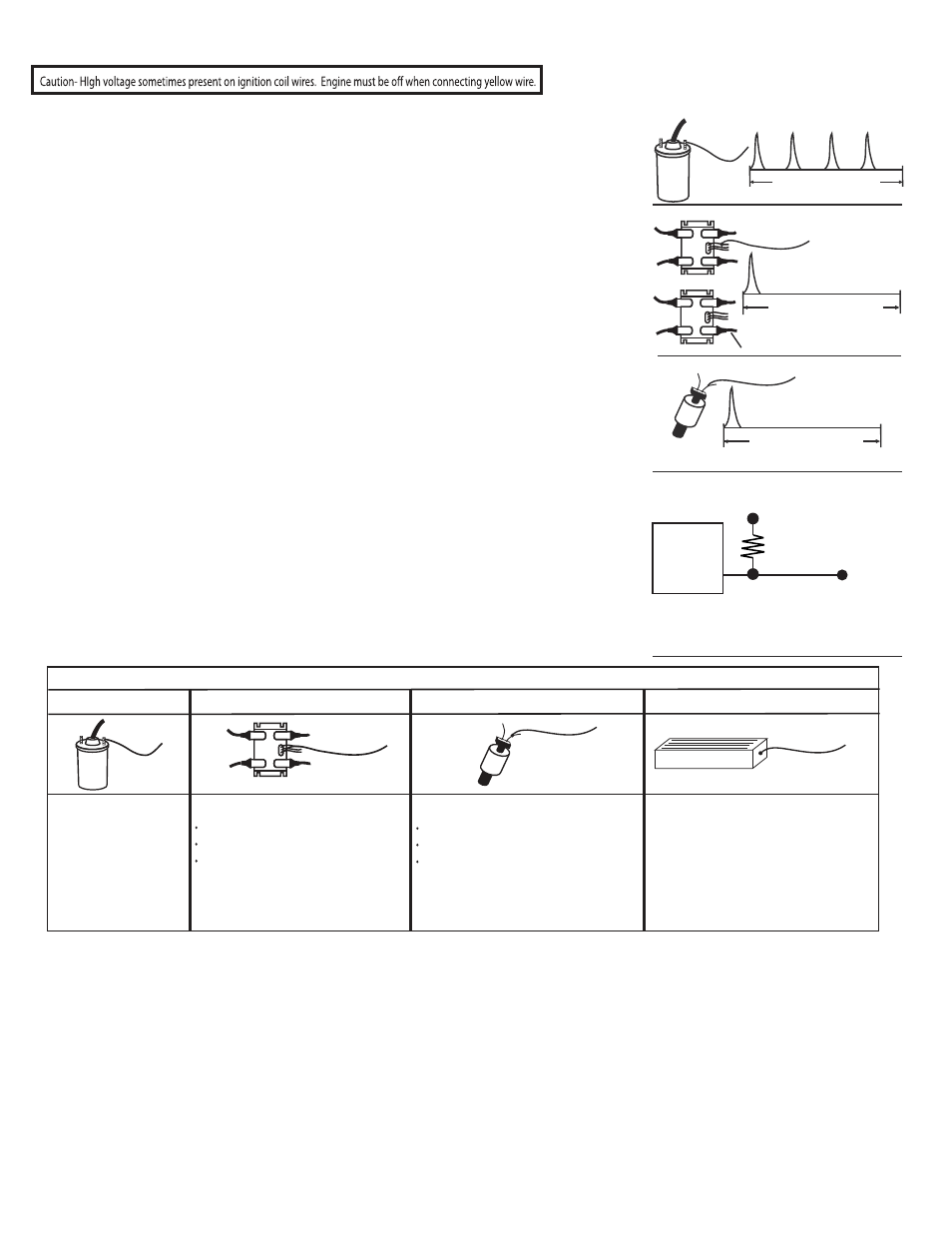
Your vehicle ignition system will fall under one of these 4 ignition types. The type of ignition system will determine where the yellow wire is
connected and what the number of pulses per revolution the tachometer should be set to.
Type #1 (single coil) - Up until the 1990’s tachometers picked up the signal from the (-) side on a single ignition coil, reading every pulse sent
to all the cylinders. For example, an 8 cylinder (4 stroke) engine fires 4 spark plugs per revolution or all 8 spark plugs in 2 revolutions.
Connecting the tachometer yellow signal wire to the negative side of the single coil on an 8 cylinder results in pickingup 4 sparks in 1 revolution
(see fig 1). This type of ignition was used pre-dominantly until the 1990’s and distributes sparks to each spark plug. In some vehicles during
the 90’s the coil and distributer merged into one unit, but it is the same ignition system - one coil that distributes sparks to all cylinders. When
connecting the yellow wire to this style of ignition you will be picking up all cylinder sparks (see fig 5).
Type #2 (coil pack) - (fig 2) is a 96 Mustang V8 with twin coil packs. Coil pack #1 (C1) controls the firing of 4 spark plugs and coil pack #2 (C2)
controls the remaining 4 spark plugs. 2 or more separate coils are within each coil pack assembly. In this example each of the 2 coils within each
coil pack sends sparks to 2 cylinders at the same time. When one cylinder is firing in the compression stroke, it’s paired cylinder is “waste” firing in
the exhaust stroke. Each separate coil within the pack is controlled by it’s own trigger wire. In other words, if you hooked up the yellow wire to one
coil trigger wire within one coil pack, it will see only a fraction of the total engine sparks (see fig 5).
Type #3 (coil on plug) – An individual coil is placed directly on top of each spark plug eliminating the spark plug wires. The yellow wire, when
hooked up to any coil, will pick up only 1 pulse per 2 revolutions or 1/2 pulse per 1 revolution (see fig 3). For this type of ignition the yellow wire
from the tachometer will connect to the trigger wire on one of the coils. Typically there will be 3 or 4 colored wires coming off of each coil. The
trigger wire will be the wire that changes color from one coil to the next. For example, all coils may have red, gray and black wires coming off of
them, but the fourth wire will be blue on one coil and green on the next coil.
Type #4 (tach output from ECU) Some vehicles will have a tachometer output wire coming from the ECU. The yellow wire from our tachometer
can receive signal from the ECU by following the diagram in fig 4. 4.7k Ω resistor and shrink tubing are included with gauge.
In summary, figure out how many cylinders you are picking up with the yellow wire and set the respective number of pulses per revolution
(see step 4). The tachometer can be configured to work on .5 pulse (coil on plug) up to 6 pulses per revolution. Use Fig 5 as a starting point
when hooking up the yellow wire.
- negative
+
Yellow wire
1 revolution of engine
8 CYL early style single coil example
(fig 1)
1 revolution of engine
8 CYL twin coil packs
(fig 2)
C2
To spark plugs
Yellow wire
C1
2 revolutions of engine
8 CYL coil on plug
(fig 3)
Yellow wire
Setup the Tachometer to run
2 pulses per rev when
connecting it to the engines’ ECU.
ECU
Tachometer (Yellow)
ACC (12v)
4.7K -10K Ω 0.25 watt minimum
(fig 4)
Type #1 ignitions
- negative
+
Yellow wire
Yellow wire connects to:
negative side of coil.
12 cyl = 6 sparks / rev
10 cyl = 5 sparks / rev
8 cyl = 4 sparks / rev
6 cyl = 3 sparks / rev
4 cyl = 2 sparks / rev
(see step #4)
Yellow wire connects to:
tachometer output terminal
12 cyl = 6 sparks / rev
10 cyl = 5 sparks / rev
8 cyl = 4 sparks / rev
6 cyl = 3 sparks/ rev
4 cyl = 2 sparks / rev
Yellow wire connects to:
negative side of coil (some cars) or
coil control wire (some cars) or
coil trigger wire (some cars).
1 spark / rev. (as a good starting point)
(see step #4)
Yellow wire connects to:
negative side of coil (some cars) or
coil control wire (some cars) or
coil trigger wire (some cars).
1/2 spark / rev. (as a good starting point)
(see step #4)
Fig 5: Tachometer yellow wire hook up options
Yellow wire
C1
g
ul
P
n
o
li
o
C
-
3
#
e
p
yT
s
kc
a
P
li
o
C
-2
#
e
p
yT
Yellow wire
Aftermarket ignitions / tach output
Yellow wire
Important note: connecting the tachometer to the wrong wire will NOT damage the tachometer or your ignition. It just won't work!
Tachometer Installation options