Electronics 590-24 User Manual
Page 14
14
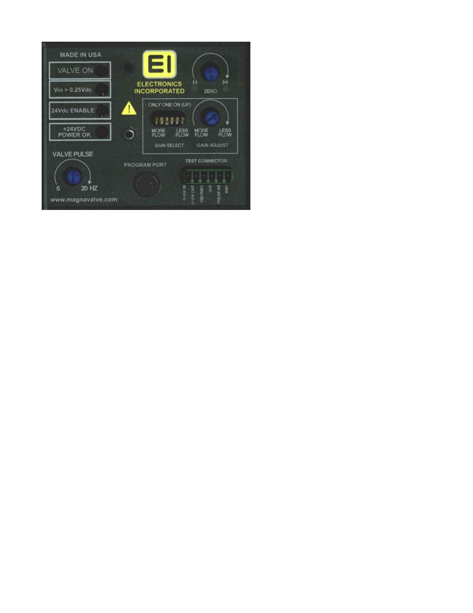
Diagnostic LED’s
VALVE ON – When this LED is on, the electromagnet is receiving power. When the LED is off, the permanent
magnets will hold or block the shot flow. When the LED is fully on the valve is on for full capacity flow rate.
When the LED is blinking, the electromagnet is regulating the shot flow.
Vin > 0.25 Vdc- This LED indicates that the valve is receiving an analog signal input greater than 0.25 Vdc.
When this LED is off there is no media flow allowed. The input signal range is 0-10 Vdc. At 10 Vdc the valve
will “open” to full capacity, which is usually 10% to 50% higher than the calibrated range. The relationship be-
tween the 0-10 Vdc input signal and actual flow rate is nonlinear. The output signal 0-10 Vdc signal is linear
and this makes accurate regulation by the FC-24 control possible.
24Vdc ENABLE – This LED indicates that the valve is receiving a 24 Vdc Enable signal. When this LED is off
the valve is inhibited, and no shot will flow. This feature is an on-off action so there is no need to disable or
remove the 0-10 Vdc input signal.
24 Vdc Power – This LED indicates that 24 Vdc is available to operate the electromagnets for media flow. It
should always be available and able to supply 2 Amps. If the LED is blinking the supply is out of recommended
operating range +/- 2VDC (22-26VDC). If the LED is Green then there is a valve failure, please call factory.
All of the LED’s must be on in order to have media flow.
FRONT PANEL
Zero – Turn adjustment until both LED’s are
OFF or blinking. This will set the output signal to
zero ± .050 Vdc during no-flow.
Gain – This section controls the amplification or
gain of the sensor signal. It has been factory set
(see label for flow range). If the gain is changed
it will be necessary to run a one minute catch-
and-weigh test to confirm the calibration. The
full scale output signal is set to 10 Vdc for cali-
bration flow range. (30lbs/min.)
Note: Be sure only one gain switch is selected
(up position). Use the “Gain Adjust” for fine ad-
justments.
Test Socket – This socket provides access to
diagnostic voltages.
1. 0-10 Vdc input
2. 0-10 Vdc output
3. 24 Vdc “Enable” input
4. 24 Vdc supply
5. 6-20 Hertz pulse rate
6. 0 Vdc common
Program Port
This is used for advanced calibration. An optional cable is
needed to use this function.
The PA-24 Program Cable. P/N: 980090
Valve Pulse – This is the rate at which the valve dispens-
es shot, similar to a heart beat rate. It is factory set to
match the best flow characteristics of the media (cast
steel, cut wire or micro-bead). Typical operation is set at 8
Hertz or mid-scale setting of the adjustment.