Electronics 590-24 User Manual
Page 13
13
24Vdc MagnaValves with built-in flow sensors operate with the model FC-24 control. These controls provide the
servo loop the function to set and maintain the shot flow rate. They can receive an analog 0-10Vdc signal from a
customer supplied remote analog voltage for the set point or they can operate independently without customer
computer interface.
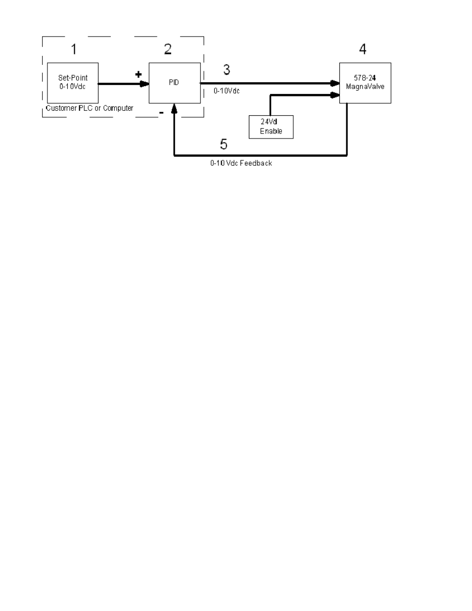
24Vdc MagnaValves can be used with customer supplied servo loop software as shown in the diagram above.
The PID sends a control signal (0-10Vdc) directly to the MagnaValve along with the 24Vdc Enable signal.
Servo Loop Theory:
A setpoint command is generated at (1) to establish the desired flow rate in pounds/minute or Kg/minute with
10Vdc representing 100% of the MagnaValve calibrated flow range. The PID function (2) will compare the set-
point to the feedback signal(5) from the MagnaValve (4). The PID output (3) will start at 0Vdc and slowly in-
crease towards 10Vdc. The PID output continues to increase until the MagnaValve feedback signal (5) matches
the setpoint value (1). At this time the PID signal (3) will hold its value to maintain the requested flow rate.
Example: If the required flow rate is 18 pounds/minute (90% of 0-20 pound/minute calibrated capacity of the
MagnaValve), the PID function would generate a slowly increasing output voltage which results in a slowly in-
creasing shot flow rate and, therefore, a slowly increasing feedback signal (5). When the setpoint signal and
feedback signal are equal, the PID output will hold its present value and the required shot flow rate will be main-
tained.
The PID output (3) is analogous to a car's cruise control. The driver will not need to know the exact position of
the gas pedal to make the car move at 55 mph. When the car goes up-hill, the gas pedal will move forward to
maintain 55 mph. As the car goes downhill the gas pedal will move back to maintain 55 mph. In a similar man-
ner, the exact voltage coming from the PID amplifier (3) is not important as long as the valve maintains 18 lbs/
min. flow rate.
PLC w/servo and MagnaValves with built-in Flow Sensors (24Vdc)
FRONT PANEL DESCRIPTION
The front panel of the MagnaValve contains the four LED’s used for diagnostics. To gain access to the factory
adjustments, remove the large knurled screw on the front cover. Please refer all adjustments to qualified per-
sonnel. Changing the gain will affect the valve calibration accuracy and should only be done when catch-and-
weigh test results are available. See figure 1 for additional information.
OPERATON
Signals used to operate the MagnaValve originate at the FC-24 Controller. There are three conditions neces-
sary for correct operation. See figure 1 for additional information.
Power – Continuously apply the 24 Vdc power to the valve. The valve requires 1.4 amps for operation
and a power supply rated at 50 VA. The voltage should be 24 ± 2 Vdc.
Enable – Use the 24 Vdc ENABLE signal to activate the valve.
Input Signal – The analog 0-10 Vdc input signal must be above 0.25 Vdc as a minimum flow command
signal.
250-24
500-24
576-24
578-24
579-24
580-24
590-24
577-24