Assembly – Grain Systems PNEG-1510 User Manual
Page 74
9. Assembly
74
PNEG-1510 Top Dry 24', 30' and 36' Manual Batch
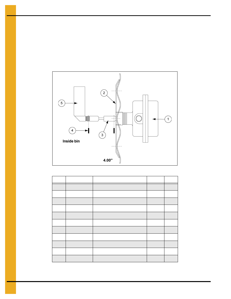
Optional Installation of Wall Mounted Rotary Switches
IMPORTANT: Wall mounted switch must be located at least 3' below the fan opening.
Drill 2" hole through wall 3' below the upper fan and heating unit(s), hole should be centered on outside valley.
Position mount plate (from inside), mark and drill 3/8" holes. Caulk coupling abundantly where it passes
through the wall. Add foam weather strip around top and sides of plate then bolt to bin wall. Caulk coupling
to wall from outside. Attach flex coupling to power-pak. Add teflon tape or pipe (sealant not included) to
power-pak pipe threads and thread in to coupling. Conduit opening should be horizontal or down. Add
1 vane paddle.
Figure 9Z Wall Mount Rotary Switch (TAF-6106)
* Hardware package not shown
- Included in hardware package
Ref #
Part #
Description
Weight
Qty
1
TD-100076
Rotary Switch Power-Pak
3.50
1
2
TD-100629
Roof Mount Coupling Weldment
2.14
1
3
TD-100075
Flex Coupling
0.50
1
4
S-7241
1/8" x 1-1/4" Cotter Pin
0.02
2
5
TAF-6085
1 Vane Paddle
0.75
1
*
TAF-6097
Hardware Package
0.98
1
-
PNEG-300
Rotary Switch Instructions
0.04
1
-
S-275
5/16"-18 x 3/4" Bin Bolt
0.16
6
-
S-3651
Tube Seal
0.74
1
-
S-396
5/16"-18 Hex Nut
0.06
6
-
S-7241
1/8" x 1-1/4" Cotter Pin
0.02
2