Rough Country 875.20 User Manual
Page 10
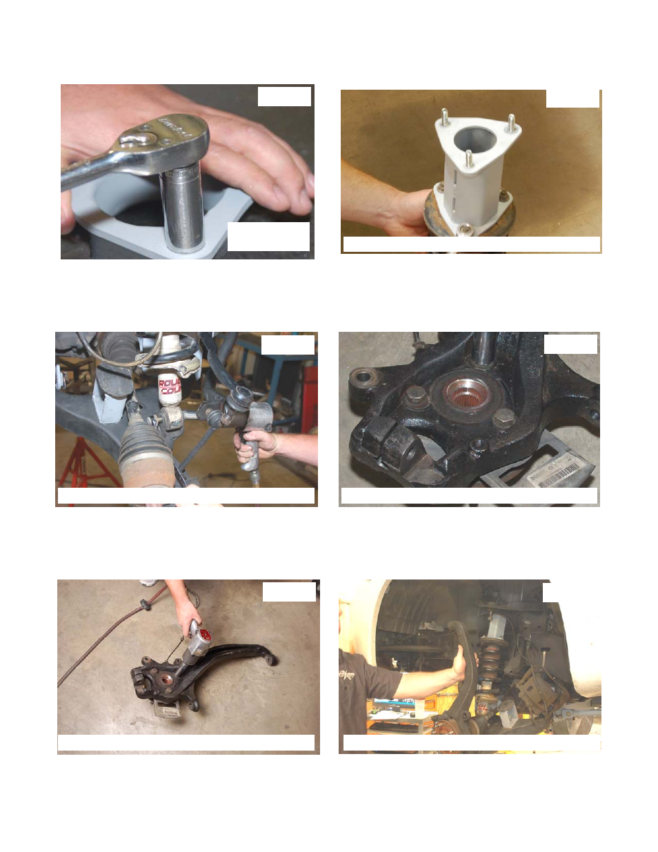
38. Install the supplied 3/8” studs on the strut spacer as shown in Photo 38 using the 3/8” nuts. Torque the 3/8” nuts to
35-45 ft\lbs to lock the stud in place.
39. Install strut spacers on the stock strut with shorter side to the back. See Photo 39. Tighten using stock hardware
with a 14mm wrench.
40. Install the strut assembly on truck using the supplied 3/8 nuts & lock washers on the upper strut spacer and stock
hardware in lower control arm strut mount as shown in Photo 40. It may be necessary to use jack stand to install the
lower bolt. Tighten using a 14mm wrench and 19mm wrench
41. Remove the wheel bearing assembly from the stock knuckle as shown in Photo 41 using a 21mm socket. Note it
may be necessary to heat slightly to break factory lock tight. Retain the factory hardware.
42. Install wheel bearing assembly into new knuckle as removed from the stock knuckle using factory hardware. See
Photo 42.
43. Install knuckle onto truck using stock hardware on the lower ball joint and upper ball joint See Photo 43. Note: The
upper control arm will pull down at full droop until it makes contact with strut tower—this is as designed and not a
problem. Be sure to line up the splines on the axle shaft with the splines on the knuckle/bearing assembly.
44. Torque the lower ball joint to 130ft/lbs with a 19mm and a17mm wrench.
45. Tighten upper ball joint with 22mm wrench.
46. The driver side and passenger side tie rod ends need to be exchanged to provide adequate tire clearance. The stud
will be facing down. Install them on the new knuckle using a 22mm wrench with stock hardware. .
47. Tighten axle nut with stock hardware using a 32mm socket.
Photo 39
Photo 40
Photo 42
Photo 43
Photo 41
Photo 38
Lock Clinch
Suds into Place
Install Strut Spacer on Strut with Shorter Side to Back
Install Strut Assembly On Lower Control Arm
Remove Wheel Bearing Assembly from Stock Knuckle
Install Bearing Assembly on New Lifted Knuckle
Install Lifted Knuckle Using Stock Hardware