Powerboard, Installation instructions – Rough Country 75113-15 User Manual
Page 10
PowerBoard
®
– Installation Instructions
Rev. T 0713
75113 pg. 10
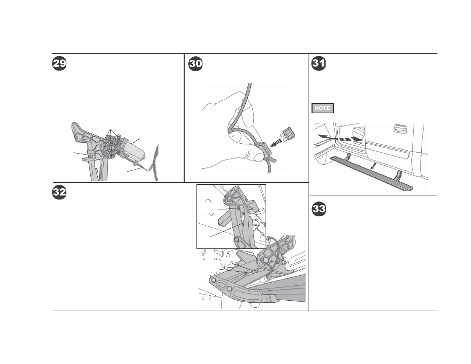
Slide Motor assembly onto drive shaft and mount-
ing bosses of Motor Linkage assembly. Use three
(3) M6-1.0 x 35mm Socket Cap Screws and (3) M6
Flat Washers to secure Motor. Plug female connector
into Motor. Wrap any exposed wires from the motor
with electrical tape.Torque the screws to 5–7 ft. lbs.
(6.78–9.49 Nm or 60-84 in. lbs.).
Install Motor
Motor
Linkage
Motor
Wire
Harness
M6-1.0 x 35mm Socket Cap Screws
and M6 Flat Washers
Reinstall the fuse in the harness.
Reinstall Fuse
Once you have checked that the Steps function
properly, reassemble the doors and reinstall the Kick
Plates and Step Plates on both sides of the vehicle.
Open the doors to make sure that the Step drops into
position on each side of the vehicle.
Cycle boards several times and then fully tighten
all bolts.
If the Step position is not even, repeat the
adjustment from Step 9.
Test Doors and PowerBoards
®
Reassemble Doors
Due to variations in vehicle build, the PowerBoards
®
may contact the vehicle body when in the up position.
If you would like to stop the board’s travel earlier, install
the supplied PSA Bumpers to the inner links or stick the
bumper to the body at the location of contact.
To stop the board travel earlier, look for the area on the
inner link where the Stop Bumper on the outer link would
make contact if the board did not stop early (see gap in
illustration).
Open the door to lower the board. Stand on the board to
keep it in the down position and shut the door. Remove
the fuse. Peel the backing off of the PSA Bumper and
stick it to the surface on the inner link where the Stop
Bumper will contact it. Do this on both idler and motor
links. Reinstall the fuse and check to make sure the Stop
Bumper hits the PSA Bumper when the doors are shut.
Install PSA Bumper – Optional
PSA
Bumper
Stop
Bumper
Stop
Bumper
Gap