VEGA VEGAPULS 61 (≥ 2.0.0 - ≥ 4.0.0) Foundation Fieldbus Approval according to LPR radio standard User Manual
Page 23
0 %
100 %
1
2
5
4
3
6
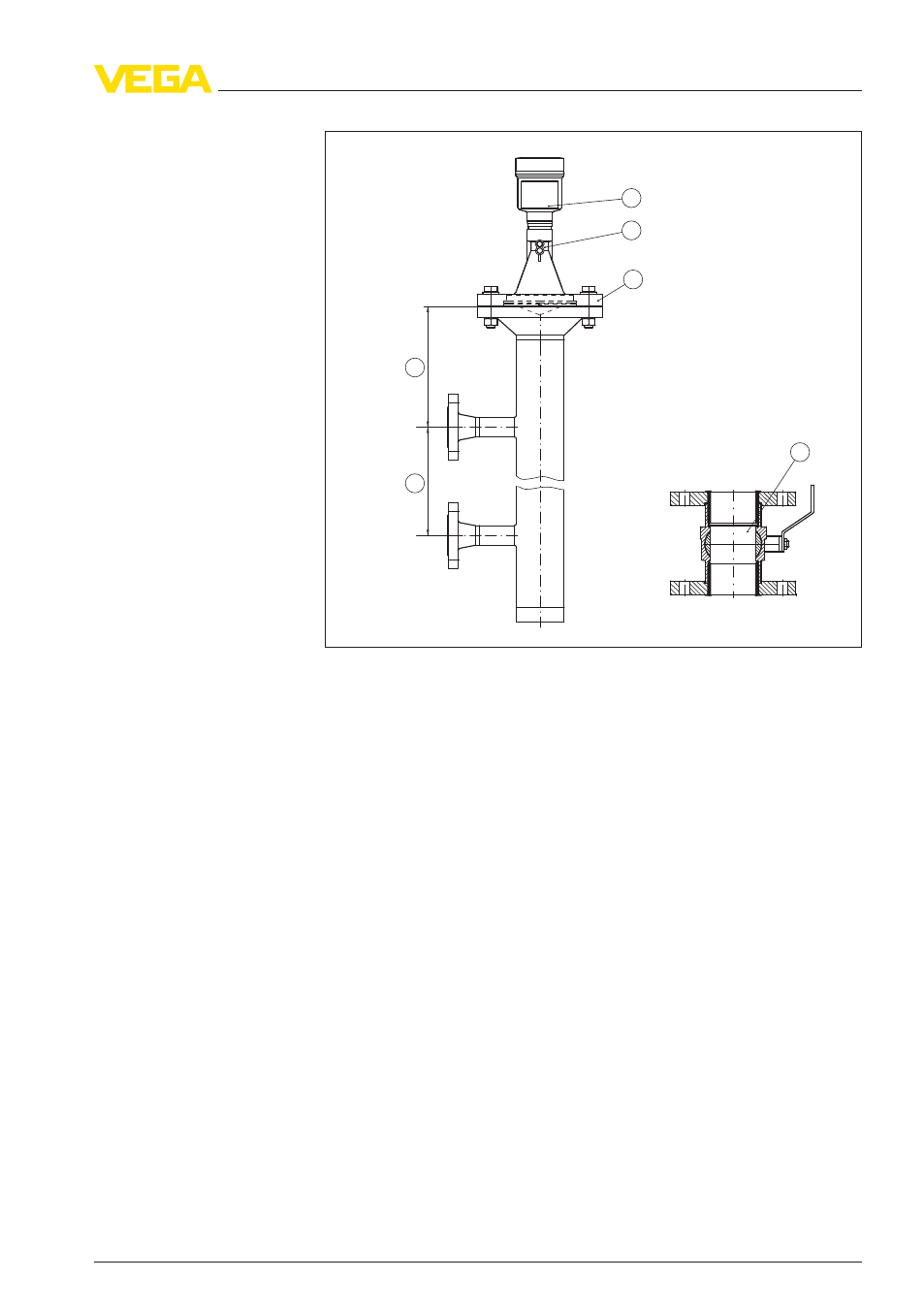
Fig. 17: Configuration bypass
1
Radar sensor
2
Marking of the polarisation direction
3
Instrument flange
4
Distance sensor reference plane to upper tube connection
5
Distance of the tube connections
6
Ball valve with complete opening
Instructions for orientation:
l
Note marking of the polarisation plane on the sensor
l
With threaded fitting, the marking is on the hexagon, with flange
connection between the two flange holes
l
The pipe connections to the vessel must be in one plane with this
marking
Instructions for the measurement:
l
The 100 % point must not be above the upper tube connection to
the vessel
l
The 0 % point must not be below the lower tube connection to the
vessel
l
Min. distance sensor reference plane to the upper edge upper
tube connection > 300 mm
l
The tube diameter must be at least DN 40 or 1½" with antenna
size 40 mm (1½")
l
For the parameter adjustment, select "Application standpipe" and
enter the tube diameter to compensate errors due to running time
shift
VEGAPULS
61 • Approval according to LPR radio standard
23
4 Mounting
41716
-EN
-120301