Measurement set-up for gases – VEGA VEGADIF 34 … 51 User Manual
Page 56
56
VEGADIF 34 … 51
20094-EN-030731
Installation connections
Instructions for both connections
- For steam flow measurements, blow down
lines should be installed. The line to the blow
down valve should be as straight as possi-
ble.
- The impulse lines must be able to dissipate
condensation heat. Hence they should not
be insulated.
- VDE/VDI regulation 3512 or different DIN
standards give additional information.
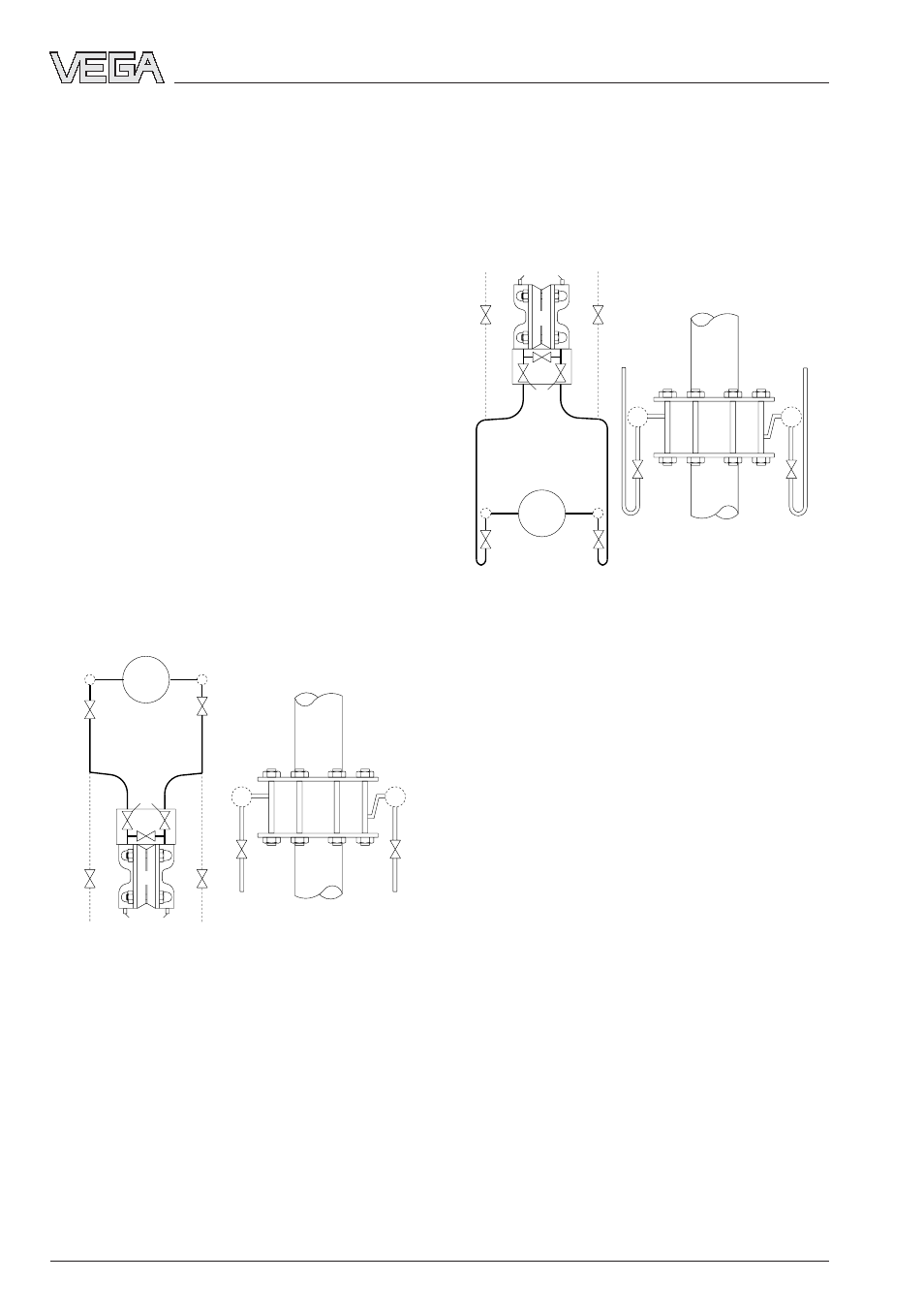
Measurement set-up for gases
Humid gases at ambient temperatures contain
a certain quantity of condensating particles.
The recommended installation position of the
transmitter is hence above the pressure tap-
ping points so that condensate can return to
the process. The arrangement prevents un-
equal condensate buildup in front of the plus
and minus side of the transmitter and the
resulting measurement errors. The impulse
lines must be run with sufficient gradient.
5
5
2
1
6
6
7
6
8
8
8
8
6
-
+
4
3
1 Inlet valve
2 Equalization valve
3 Transmitter
4 Vent or drain valve
5 Blow down valve (if needed)
6 Block valve
7 Effective pressure transmitter
8 Adjustment pots
With dry gases, the transmitter can be in-
stalled above as well as below the pressure
tapping points. Also in this case, the impulse
lines must be run with sufficient gradient so
that condensate can flow to the drainage
valves.
1 Inlet valve
2 Equalization valve
3 Transmitter
4 Vent or drain valve
5 Blow down valve (if needed)
6 Block valve
7 Effective pressure transmitter
8 Adjustment pots
Instructions for corrosive gases
If the measuring cell needs to be protected
against very corrosive gases, an arrangement
with protective vessels acc. to VDE/VDI 3512
should be implemented. As an alternative, the
method of protective gas flushing can be
implemented - it is applicable for corrosive
gases with impurities.
5
5
2
1
6
6
7
6
8
8
8
8
6
-
+
4
3