3 electrical connection, 1 connection instructions, 2 load resistance – VEGA VEGADIF 34 … 51 User Manual
Page 28
28
VEGADIF 34 … 51
20094-EN-030731
Electrical connection
3 Electrical connection
3.1 Connection instructions
The electronics of the pressure transmitters
requires a supply voltage of 11.5 … 45 V DC.
Supply voltage (DC voltage) and current
signal are carried over the same two-wire
connection cable to the terminals.
The supply voltage is provided via a separate
power supply unit:
- power supply unit
(e.g. VEGASTAB 690)
- processing unit with integrated DC voltage
source (e.g. active PLC input)
- VEGAMET series 500 or 600 signal condi-
tioning instrument, VEGALOG 571 process-
ing system or VEGADIS 371 indicating
instrument
Make sure that the external energy source is
reliably separated from the mains circuits acc.
to DIN VDE 0106, part 101. VEGA instruments
meet this requirement and protection class III
is therefore maintained.
For electrical connection note the following
instructions:
- The connection must be made acc. to the
specific national installation standards (e.g.
in Germany acc. to the VDE regulations).
- The wiring between transmitter and power
supply can be carried out with standard
two-wire cable.
- If strong electromagnetic interference is
expected, screened cable is recom-
mended. The screening must be earthed at
one sensor end.
- The connection cable for the external en-
ergy must never be connected to terminal 3
of the terminal block or to the test plug con-
nection via terminal 1 of the terminal block
(danger of damaging the electronics).
- After electrical connection, housing cover
and cable entry must be tightened to avoid
moisture ingress in the connection compart-
ment
3.2 Load resistance
Various instruments can be connected to the
signal output of the pressure transmitter, e.g.:
- remote transmission systems
- computers
- indicating instruments
- recorders
- controllers
- contactors etc.
The total resistance of the connected instru-
ments and the connection cable must not
exceed the value of the max. load resistance.
The load resistance consists of the line resist-
ance R
L
, adjustment resistance R
X
, and the
resistance of the processing system and/or
indicating instrument.
This max. load resistance depends on the
voltage of the external energy and can be
calculated acc. to the following formula:
U
S
– U
K
R
Lmax
= –––––––––
I
max
R
Lmax
= max. load resistance
U
S
= power supply
U
Kl
= terminal voltage
I
max
= max. current (approx. 23 mA)
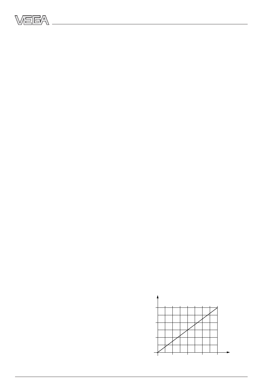
The following load diagram is used for simpli-
fied determination of this value:
500
1000
1560
20
28,5
37
45
11,5
0
Power supply U
S
in Volt
Load R
total
in Ohm