Vegadif 34, 35, Installation on closed vessels – VEGA VEGADIF 34 … 51 User Manual
Page 48
48
VEGADIF 34 … 51
20094-EN-030731
VEGADIF 34, 35
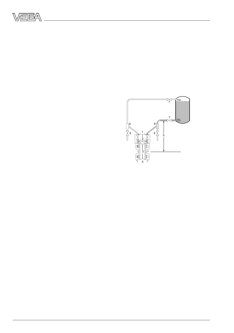
Standard installation connection
The transmitter should be installed preferably
at the height of the planned pressure tapping
point. If a location below the lower pressure
tapping point is planned, the height difference
„h“ (to the centre of the measuring cell) be
taken into account in the adjustment of zero
and span.
1 Inlet valves
2 Equalization valves
3 Transmitter
4 Vent or drain valves
5 Blow down valves
6 Separator for impurities
7 Block valves
Note:
- Unlike single pressure transmitters differen-
tial pressure transmitters are selected only
according to the expected pressure differ-
ence. As long as the overlaid pressure
does not exceed the permissible nominal
pressure, it does not have to be taken into
account. The selected measuring range can
thus be perfectly adapted to the expected
pressure difference.
- The described connections are recom-
mended measurement set-ups. For other
measurement set-ups, various VDE/VDI
regulations or DIN standards (e.g. VDE/VDI
3512) provide further installation instruc-
tions.
Installation connections
This installation has the advantage that zero
and span can be checked/modified without
emptying the vessel. Valve 3 enables the
necessary venting/emptying of the tapping
socket.
Installation on closed vessels
In a closed, pressurised vessel, the level of
the medium is determined by measuring the
hydrostatic pressure. The sum of the liquid
hydrostatic pressure and the overlaid pres-
sure is the total pressure acting on the bottom
of the vessel. The hydrostatic pressure is
therefore the difference between the total
pressure and the overlaid pressure.
The hydrostatic pressure corresponds to the
level of the product, measured from the centre
of the flange isolating diaphragm, multiplied by
the specific gravity of the product (because
the overlaid pressure acts on the plus side as
well as on the minus side of the transmitter, it is
compensated in differential pressure genera-
tion).
∆
p =
ρ
• g • h
∆
p: hydrostatic pressure [N/m
2
]
ρ
:
density of the fill fluid [kg/m
3
]
g:
acceleration due to gravity [m/sec
2
]
h:
level [m]
With this installation a blow down valve and a
separator for impurities are recommended for
the impulse line. This measure is not neces-
sary if the medium is clean and the formation
of buildup or sludge in the pipelines is not
expected.