3 mounting, Pipe mounting, Unf or m10 x 18 – VEGA VEGADIF 34 … 51 User Manual
Page 24
24
VEGADIF 34 … 51
20094-EN-030731
+
-
Z S
+
-
Z S
165
105
9
312,5
2.3 Mounting
2.3.1 VEGADIF 34, 35 and 51
As a rule, the differential pressure transmitter
must be firmly mounted. There are three
mounting options for VEGADIF 34, 35 and 51:
- pipe mounting (2“ pipe)
- wall mounting
- mounting on a valve block
1)
Simply hanging the transmitter on the pres-
sure lines is not recommended and is not
permitted with capillary lines.
For correct mounting, VEGA offers a universal
mounting kit consisting of:
- a mounting bracket
- a pipe shackle for 2“ pipes (up to outer-ø
63 mm)
- two hexagon nuts M8 with plain washers
- four hexagon screws (
7
/
16
UNF or
M10 x 18
2)
)
For easy removal of the transmitter, a three or
five valve manifold (ball valve fitting) can be
connected
1)
.
In this case, the valve block can be mounted
with the mounting kit to a pipe or wall instead
of the transmitter. This mounting option en-
sures easy mounting and dismounting of the
transmitter without interrupting the process.
The impulse lines can be sealed via the valves
and the manifold with the connected impulse
lines can be left in place after removal of the
transmitter.
Mounting
1)
not with VEGADIF 51
2)
M12 x 18 with 420 bar version of VEGADIF 35
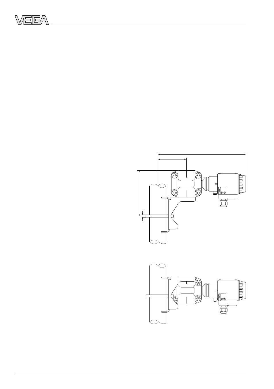
Pipe mounting
Use the complete mounting kit material and
the take note of the following procedure:
1 Hold the mounting bracket in the required
direction on the tube.
2 Insert the u-bolt around the pipe through the
holes of the mounting bracket.
3 Screw the two hexagon nuts to the u-bolt
and fasten the bracket to the pipe by tight-
ening the nuts.
4 Fasten the transmitter to the bracket (the
screws with plain washers pass through the
holes of the bracket into the thread).
Mounting on vertical pipe
approx. dimensions in mm