4 set-up, 1 adjustment structure, 2 adjustment with the 4-key adjustment element – VEGA VEGADIF 34 … 51 User Manual
Page 32: Lc display in operating mode, Adjustment program vvo, Hart, Handheld, Key adjustment elements with lc- display
32
VEGADIF 34 … 51
20094-EN-030731
- 0 .5 0 0
-0,5 bar
4 mA
- 0 .0 0 0
0 bar
8 mA
0 .5 0 0
0,5 bar
12 mA
1 .0 0 0
1 bar
16 mA
1 .5 0 0
1,5 bar
20 mA
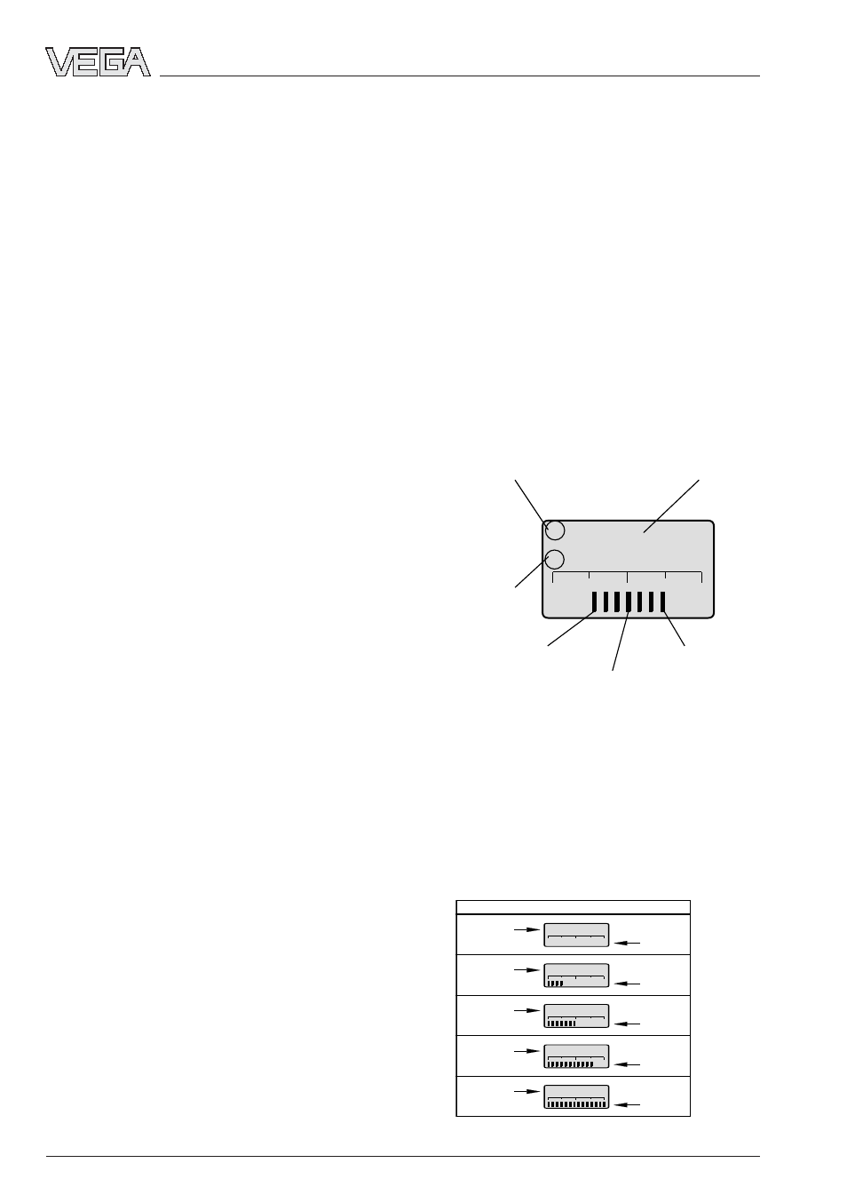
Display
I
5 .0 0 0
s
z
Span indication during
full adjustment
Appropriate
pressure value
Position of
span
Position of
zero
Zero indication during
empty adjustment
Bar graph measuring
span = span – zero
4.2 Adjustment with the 4-key
adjustment element
LC display in operating mode
According to the ordered version, your
VEGADIF is provided with an integrated LC-
display. This display can be retrofitted or
removed. The display is located below the
upper housing cover behind a glass pane.
The LC display provides the following informa-
tion in the adjustment mode:
The following examples show possible indica-
tion values.
Example 1: Meas. range -0.5 … 1.5 bar, LCD
in operating mode
LC-display
∆
p
Set-up
4 Set-up
4.1 Adjustment structure
The differential pressure transmitters can be
set up with
- the PC and the VEGA adjustment program
VVO,
- the HART
®
handheld or
- the integrated 4-key adjustment elements.
Adjustment program VVO
The adjustment program VVO (VEGA Visual
Operating) on the PC allows very convenient
sensor adjustment. The PC communicates via
the interface converter VEGACONNECT 2 with
the sensor. During adjustment, a digital adjust-
ment signal is superimposed on the signal
and supply cable. The adjustment can be
carried out a any point along the signal cable,
and of course also directly on the sensor.
HART
®
handheld
Beside the PC and the 4-key adjustment ele-
ments, the sensors can be also adjusted with
the HART
®
handheld.
4-key adjustment elements with LC-
display
If you have neither a PC nor a HART
®
handheld, the sensors can be also set up
directly with the integrated 4-key adjustment
elements.