3 connection, Electronics powered by a power supply unit, Processing via an indicating instrument – VEGA VEGADIF 34 … 51 User Manual
Page 29: Electrical connection
VEGADIF 34 … 51
29
20094-EN-030731
1
+
2
-
3
4 ... 20 mA
+
-
!
Note:
An ammeter for local testing of the output current can be connected to terminals 1 and 3 as well
as their tag. This measurement can be made during operation without interrupting the supply
cable.
~
+
-
1
+
2
-
3
4 ... 20 mA
+
-
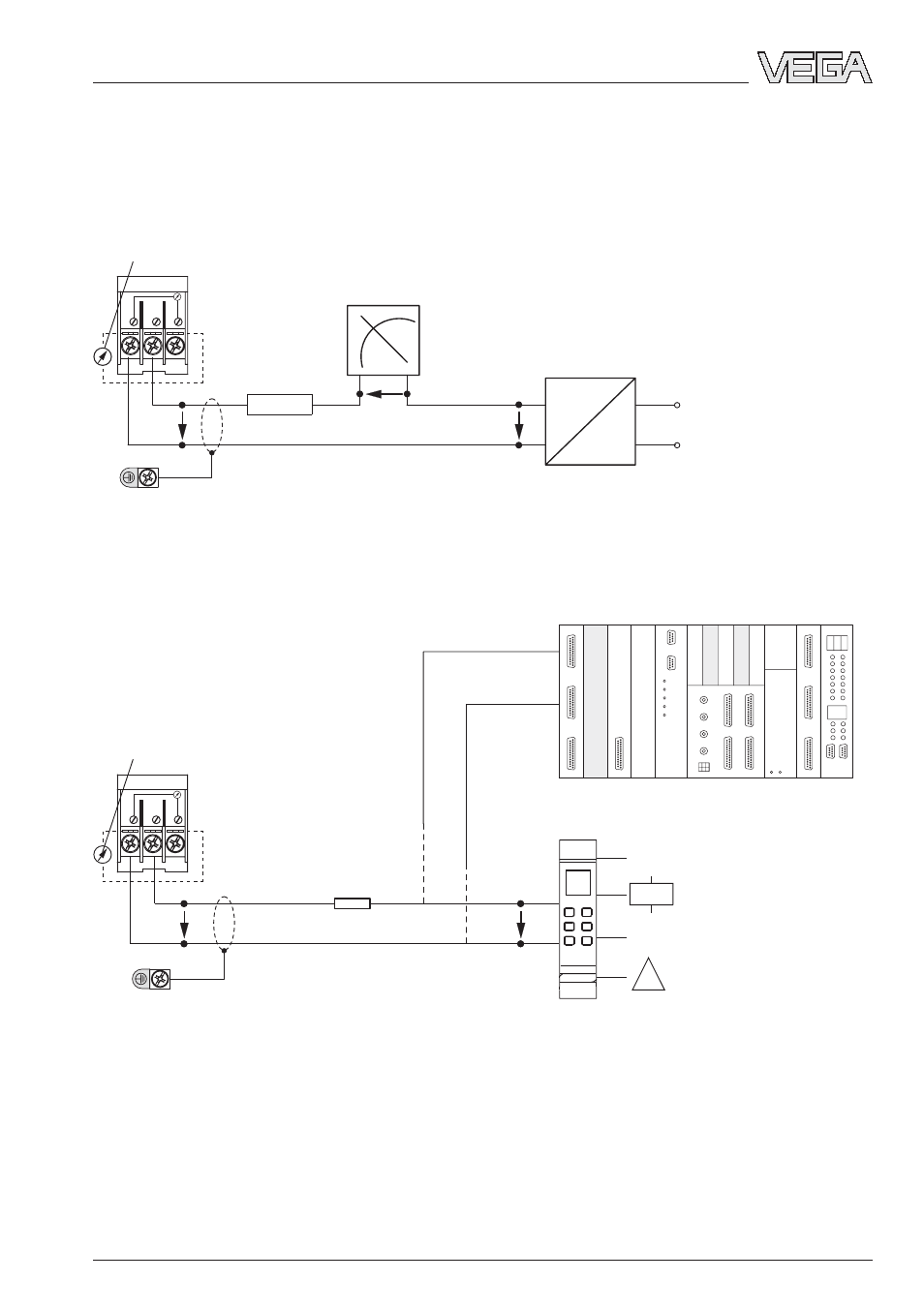
3.3 Connection
Electronics powered by a power supply unit
Processing via an indicating instrument.
Electronics powered by a VEGA signal conditioning instrument or a PLC with active
input circuit
Processing is made via the PLC or the VEGAMET signal conditioning instrument.
Ammeter for local testing
analogue / digital
indicating instrument
e.g. VEGADIS
Transmitter
terminals
Power supply
4 … 20 mA
U
Kl
U
A
U
S
Ammeter for local control
4 … 20 mA
Transmitter
terminals
0/4 … 20 mA
U
Kl
U
S
DISBUS
R
L
R
L
Electrical connection
U
S
= Power supply
U
A
= Voltage loss in the indicating instrument
U
KL
= Terminal voltage (supply voltage)
R
L
= Resistance processing systems and connec-
tion cable (load resistance)
or
PLC active
Ground terminal
1)
Ground terminal
1)
1)
Connect screen, here, ground terminals on the
housing exterior acc. to regulations. The two
terminals are galvanically connected.
Screen
Screen
–
+