3 isolating diaphragm mounting with vegadif 51 – VEGA VEGADIF 34 … 51 User Manual
Page 26
26
VEGADIF 34 … 51
20094-EN-030731
;;
;;
;;
;;
;;
;;
;;
;;
;;
;;
;;
;;
;;
;;
;;
;;
;;
;;
Min.
Max.
Min.
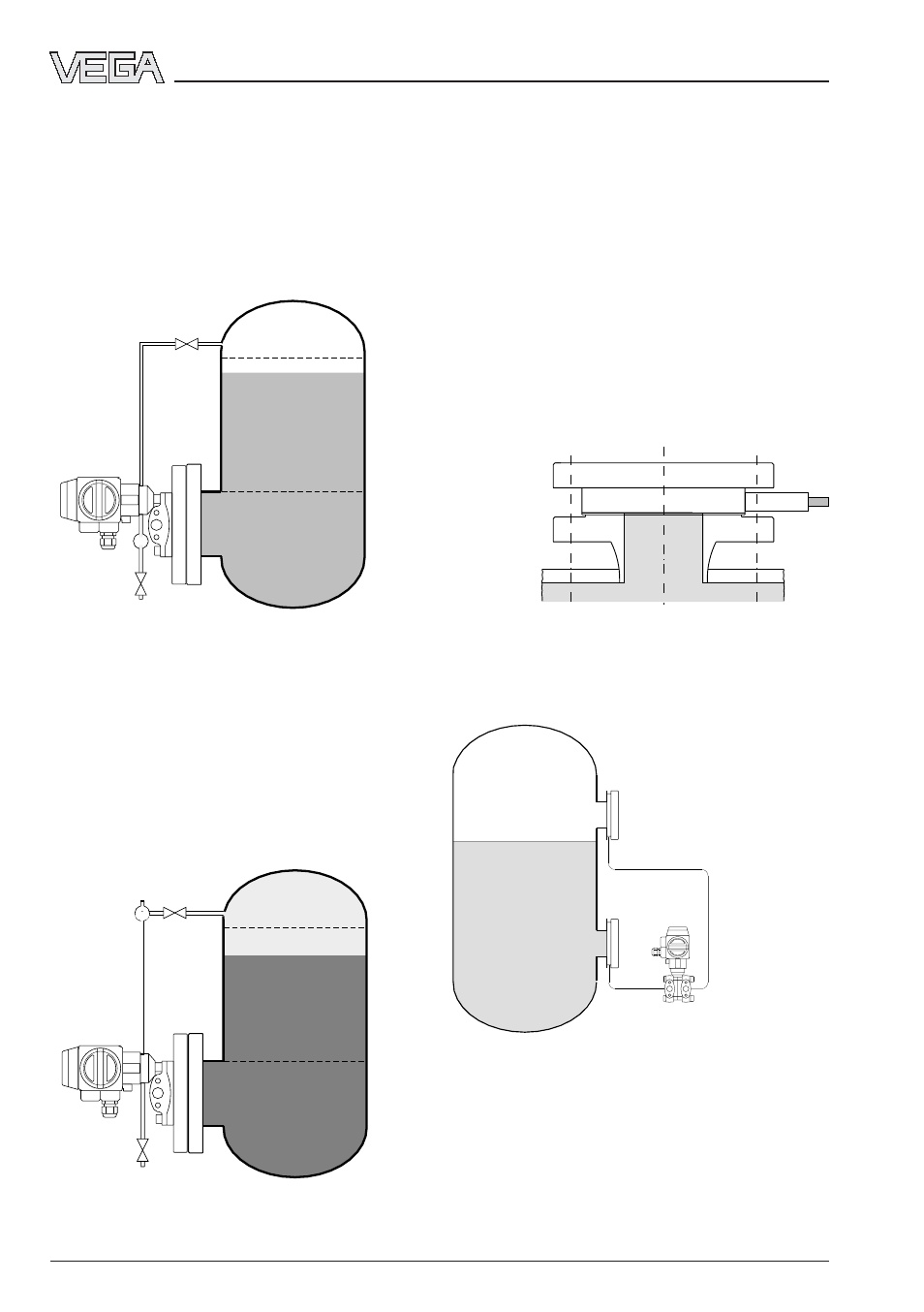
2.3.3 Isolating diaphragm mounting
with VEGADIF 51
The two isolating diaphragms connect the
pressure transmitter with the process. The
dimensions of the cell isolating diaphragm are
dependent on the respective standard flange.
The fastening is made by means of a suitable
blind flange. Depending on the flange, a seal
acc. to DIN 2690 or ANSI B 16.5 must be
used.
Mounting
Level measurement
Recommended mounting
;;;;;;;;;;
;;;;;;;;;;
;;;;;;;;;;
;;;;;;;;;;
;;;;;;;;;;
;;;;;;;;;;
;;;;;;;;;;
;;;;;;;;;;
;;;;;;;;;;
;;;;;;;;;;
;;;;;;;;;;
;;;;;;;;;;
;;;;;;;;;;
;;;;;;;;;;
;;;;;;;;;;
;;;;;;;;;;
;;;;;;;;;;
;;;;;;;;;;
;;;;;;;;;;
;;;;;;;;;;
;;;;;;;;;;
;;;;;;;;;;
;;;;;;;;;;
;;;;;;;;;;
;;;;;;;;;;
;;;;;;;;;;
;;;;;;;;;;;;;;;;;;;;;;;;;;;;
;;;;;;;;;;;;;;;;;;;;;;;;;;;;
;;;;;;;;;;;;;;;;;;;;;;;;;;;;
;;;;;;;;;;;;;;;;;;;;;;;;;;;;
;;;;;;
;;;;;;;
Mounting
Closed vessel
The minus side of the transmitter is connected
via an impulse line with the vessel and re-
ceives the overlaid pressure. The pressure
tapping point must be above the max. level.
The impulse line should equipped with a block
valve.
If the static pressure is caused by steam
above the product, the minus side is con-
nected via a condensate column. Before
opening the block valve, the impulse line must
be filled via the condensation pot.
Block
valve
Block
valve
Steam trap
Block
valve
Block
valve
Condensa-
tion pot
Steam
Condensa-
tion outlet
Condensate
Vessel wall
Measurement
loop connec-
tion flange
Seal
Blind flange
Isolating dia-
phragm