Installation guide, Installation, cont, Mounted data acquisition board – Veris Industries H704-42_1(H)(E) Install User Manual
Page 4: 50” distance between bracket screws
6%2)3
H704
INSTALLATION GUIDE
Z202366-0M
page 4
©2008 Veris Industries USA 800.354.8556 or 503.598.4564 / [email protected]
02081
installation, cont.
2.
Disconnect power to the electrical panel and lock it out. Connect 2-wire
120 VAC* power to power terminals. (see Product Diagram for location) Observe
polarity.
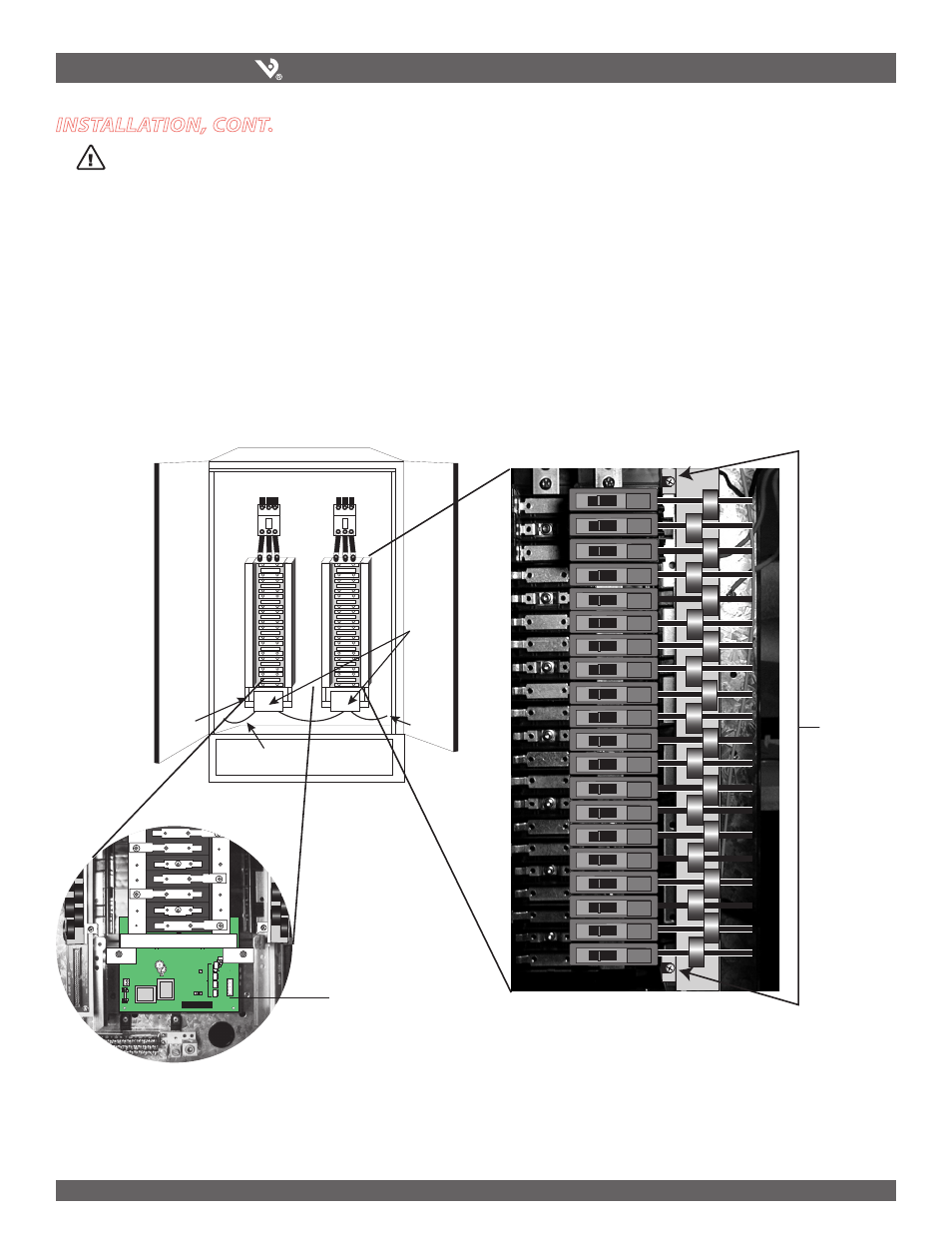
3. Current Sensor Strip Installation: Locate panel board screws which are 16.50”
(420 mm) apart and allow the current sensors to line up directly with breaker
terminations. Loosen these two screws sufficiently for the brackets (1 & 2) to slip
under screws. Do not remove screws completely. Slide the current sensor strip
mounting bracket under these loosened screws. Be sure to face the inside of the
bracket toward the breakers. Tighten screws. Repeat for the other side of the panel
board.
4. Check that CT serial numbers and meter serial numbers match. Meter and CT sold
as set with accuracy calibrated as a set.
* For 208/230VAC Power Connection version, order H704-42E/H704-42/IE
(
5
2
2
%.
4
3%
.
3/
2
42
)0
(
5
2
2
%.
4
3%
.
3/
2
42
)0
(
5
2
2
%.
4
3%
.
3/
2
42
)0
(
5
2
2
%.
4
3%
.
3/
2
42
)0
(
$ATA
!CQUISITION
"OARD
-ODBUS
5P
( gS
2IBBON
#ABLE
4O
OR
0ANEL
0ANEL
6
4
2
12
10
8
18
16
14
24
22
20
30
28
26
36
34
32
42
40
38
4
LEFT
RIGHT
RX
Mounted
Data Acquisition Board
20
20
20
20
20
20
20
20
20
20
20
20
20
20
20
20
20
20
20
20
16.50”
distance
between
bracket
screws
5. Acquisition Board Installation: Find screw holes under panel board in side
of PDU chassis or panel. Attach Data Acquisition Board bracket using screws and
bolts provided.
6. Pass power wiring through appropriate CT's observing local code for bending
radius. Current sensors accommodate for #6 THNN sized conductor. (max.
diameter 0.35”/9 mm). Use insulated wire only.