Installation guide, Installation – Veris Industries HW PROTOCOL SERIES Install User Manual
Page 2
Z205863-0C
PAGE 2
©2012 Veris Industries USA 800.354.8556 or +1.503.598.4564 / [email protected]
01122
Alta Labs, Enercept, Enspector, Hawkeye, Trustat, Veris, and the Veris ‘V’ logo are trademarks or registered trademarks of Veris Industries, L.L.C. in the USA and/or other countries.
TM
HW PROTOcOL
INSTALLATION GUIDE
correct
incorrect
Five screwholes available; use a mini-
mum of two for secure mounting.
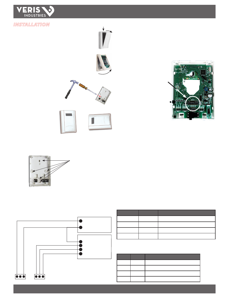
INSTALLATION
1. Remove the cover by pressing the tab at the top of the sensor while
pulling outward from the top of the cover.
2. Remove the backplate by unfastening the sensor from the bottom
of the backplate and pivoting the sensor outward.
3. Punch out openings in the backplate.
4. Position the sensor vertically on
the wall, 4 1/2 feet above the
floor.
5. Mount the backplate onto the wall using the screws provided.
6. Wire the backplate.
Wire the RS-485 connections with shielded, twisted-pair wire, such as Belden Cable
1120A or equivalent. With 2-wire cable, connect the shield at one end only to the
RS-485 SHIELD terminal.
POWER SUPPLY
12-30VDC, 24VAC
CONTROL SYSTEM
COMMON
RS-485+
RS-485 -
SHIELD
PWR
GND
RS
-485+
RS
-485-
SHIELD
+
-
-
DIP switches, located on backside of board,
Top row: Address switches
Bottom row: Configuration switches
Select Address DIP switches
1. Up for Modbus, Down for BACnet.
2. Up to add 64 to network address.
3. Up to add 32 to network address.
4. Up to add 16 to network address.
5. Up to add 8 to network address.
6. Up to add 4 to network address.
7. Up to add 2 to network address.
8. Up to add 1 to network address.
The network address is the sum of the values selected by placing switches 2
through 8 in their UP position. E.g.: If switches are D D D U D U D D, then BACnet
communication is selected, and the address is 16 + 4, for a total of 20. Valid Modbus
addresses are 1 to 127, and valid BACnet addresses are 0 to 127. Each device on the
daisy chain must have a unique address.
Select Configuration DIP switches
Configuration DIP switches 1 and 2 control the parity settings for Modbus and have
no effect on BACnet communication, which never has parity.
Switch 1
Switch 2
Parity
Down
Down
None (2 stop bits)
Down
Up
Odd
Up
Up
Even
Up
Down
None (1 stop bit; common but non-standard)
Configuration DIP switches 3 and 4 control the data rate for both Modbus and BACnet
modes.
Switch 3 Switch 4
Data Rate
Down
Down
9600 bps
Down
Up
19200 bps
Up
Down
38400 bps
Up
Up
Modbus: 57600 bps; BACnet: 76800 bps
Ground each unit via the power supply GND terminal or the RS-485 SHIELD terminal
if the power supply is floating. Grounding is necessary to minimize common mode
voltage on the signal lines and to minimize radio frequency emissions that can
interfere with the operation of nearby radio equipment.
Daisy-chain devices with 120Ω termination resistors between RS-485+ and RS-485-
on the last device at each end of the chain. Maximum of 63 devices on one daisy
chain.
7. Configure the sensor.
Set the DIP switches on the backside of the
board.