Veris Industries HW PROTOCOL SERIES Install User Manual
Hw protocol, Notice, Installation guide
Z205863-0C
PAGE 1
©2012 Veris Industries USA 800.354.8556 or +1.503.598.4564 / [email protected]
01122
Alta Labs, Enercept, Enspector, Hawkeye, Trustat, Veris, and the Veris ‘V’ logo are trademarks or registered trademarks of Veris Industries, L.L.C. in the USA and/or other countries.
TM
ENVIRONMENTAL SENSORS
INSTALLATION GUIDE
Wall Mounted Humidity Sensors
with Protocol Communication
Installer’s Specifications
Input Voltage
12 to 30VDC, 24VAC; 100mA max.
Operating Temperature Range
0° to 50°C (32° to 122°F)
Housing Material
High impact ABS plastic , UL 94 VO
Protocol
BACnet or Modbus (selectable)
Connection
2-wire RS-485
Data Rate
9600, 19200, 38400, 57600 (Modbus), bps (selectable)
9600,
19200, 38400, 76800 (BACnet), bps (selectable)
Parity
None/Odd/Even (selectable-Modbus)
None
(BACnet)
Address Range 1-127
RH Transmitter:
HS Sensor
Replaceable digitally profiled thin-film capacitive
(32-bit
mathematics); U.S. Patent 5,844,138
Accuracy*
±1% from 12 to 60% RH; ±2% from 10 to 80% RH;
NIST
traceable multi-point calibration
Reset Rate**
24 hours
Stability
±1% @ 20°C (68°F) annually for two years
Hysteresis
1.5% typical
Operating Humidity Range
0 to 100% RH, noncondensing
Operating Temperature Range
10° to 35°C (50° to 95°F)
Temperature Coefficient
±0.1% RH/°C above or below 25°C (typical)
Temperature Transmitter Option:
Sensor Type
Solid-state, integrated circuit
Accuracy
±0.5°C (±1°F) typical
Resolution
0.1°C (0.2°F)
Range
10° to 35°C (50° to 95°F)
Setpoint Slider Resolution Option
1% full scale
Override Button Option
Remotely readable and resettable
* Specified accuracy with 24VDC supplied power with rising humidity.
** Reset rate is the time required to recover to 50% RH after exposure to 90% RH for 24 hours.
Note: RTD/Thermistors in wall packages are not compensated for internal heating of product.
HW Protocol
HW Protocol
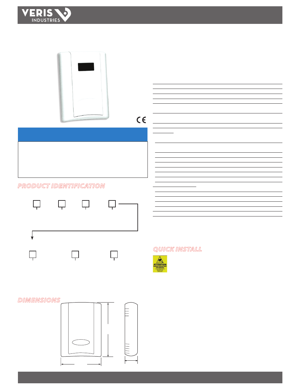
DIMENSIONS
NOTICE
• This product is not intended for life or safety applications.
• Do not install this product in hazardous or classified locations.
• Read and understand the instructions before installing
this product.
• Turn off all power supplying equipment before working on it.
• The installer is responsible for conformance to all applicable codes.
PRODUCT IDENTIFICATION
QUICK INSTALL
1. Select a mounting location away from ventilation sources. The sensor should be
mounted on a vertical wall, about 4 1/2 feet above the floor.
2. Affix the backplate to the wall.
3. Wire the device. Refer to wiring diagram.
4. Install Cover.
HW
Local Display
L = LCD
X = No Display
Protocol
= Protocol
P
RH Option
1 = RH 1% NIST
2 = RH 2% NIST
H = RH 2%
Temp. Option
X = No temp. option
T = Temp. Transmitter
Temp. Cal. Cert.
X = No
1 = 1 pt. cal. cert.*
2 = 2 pt. cal. cert.*
3 = 3 pt. cal. cert.*
Option
Blank = None
1 = Pushbutton override
2 = Setpoint slider
3 = Pushbutton override +
set point slider
Housing
Blank = Cloud white
B = Black
4.8"
(122 mm)
1.2"
(30 mm)
3.5"
(89 mm)
T
Observe handling precautions for static sensitive
devices to avoid damage to the circuitry which
would not be covered under the factory warranty.
* Only available if temperature option is selected.