Installation guide, Installation – Veris Industries H8053 Install User Manual
Page 3
H8051/H8053
Z201659-0N
PAGE 3
©2011 Veris Industries USA 800.354.8556 or +1.503.598.4564 / [email protected]
12112
Alta Labs, Enercept, Enspector, Hawkeye, Trustat, Veris, and the Veris ‘V’ logo are trademarks or registered trademarks of Veris Industries, L.L.C. in the USA and/or other countries.
TM
INSTALLATION GUIDE
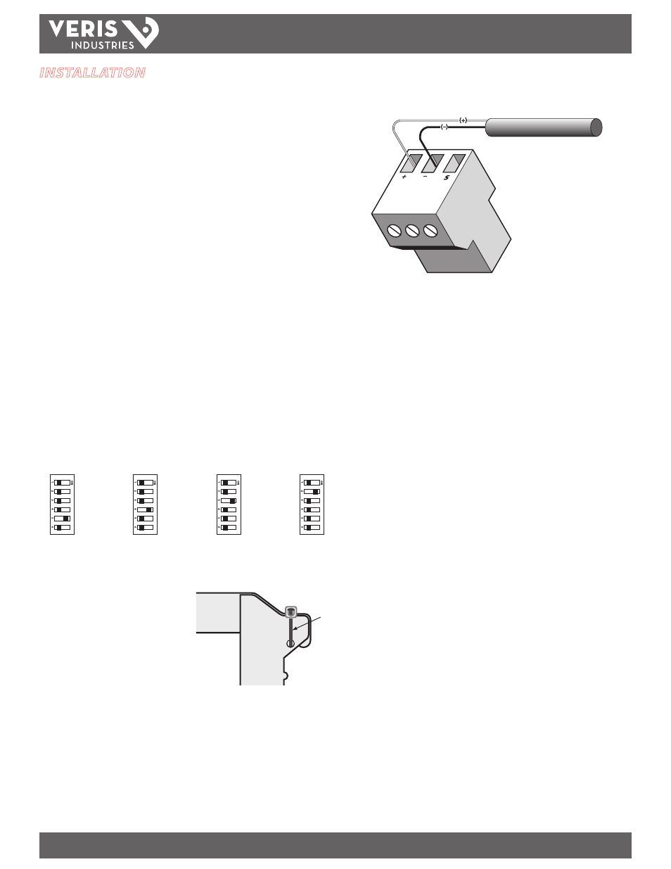
4. Attach the pulse output wires as shown. Observe (+) and (-) polarity. Insulate any
exposed wiring.
5. Check power reading (these calculations are approximations only).
Expected power:
single-phase kW = Volts x Amps x PF / 1000
3-phase kW = Volts x Amps x 1.732 x PF / 1000
kW = Horsepower x 0.746
Seconds per pulse:
S = kWh pulse setting
seconds/pulse = (3600 x S) / kW
INSTALLATION
Disconnect and lock out power to the enclosure before
installation.
The Enercept meter, including the current transformers (CTs), voltage connection
fuses, and fuse pack, is permitted within electrical distribution equipment
including but not limited to panelboards, switchboards, motor control centers, and
transformers. Carefully review the equipment in which the Enercept meter will
be installed. Consider the following installation conditions during the installation
process:
• Review the equipment enclosure for ventilation openings. Wires will cross
many of these openings in a normal installation; however, do not install
the Enercept where it will substantially block ventilation openings in the
enclosure.
• The Enercept meter and the wiring installed within a wiring space or
gutter should not exceed 75% cross sectional fill at the Enercept meter
parts as addressed in the NEC. Improper installation of Enercept meter in
the wire gutter of equipment may affect the thermal performance of the
equipment.
• Consider the arrangement of CTs within the equipment to ensure
adequate bending radius of conductors.
• Review the arrangement and location of the CTs within the equipment.
Do not create undue strain on the conductor. A CT may require
appropriate support in order to address such a condition.
1. Set the DIP switches for the desired pulse rate as shown. Not all settings are
allowed for each model.
kWh/pulse
0.1 KWH PER PULSE
Not allowed on 1600A
and 2400A models
0.10
0.25
0.50
1.00
kWh/pulse
0.25 KWH PER PULSE
Not allowed on
2400A model
0.10
0.25
0.50
1.00
kWh/pulse
0.50 KWH PER PULSE
All models
0.10
0.25
0.50
1.00
kWh/pulse
1 KWH PER PULSE
All models
0.10
0.25
0.50
1.00
2. Connect the voltage leads to the conductors, at a location that is not normally
turned off. Connect voltage leads on the line side of the conductor to ensure
constant power to the meter. See the
Wiring section.
3. Snap the CT onto the conductor. If the
application can exceed 20 times the
rated CT current, use wire ties to secure
the I-bar to the CT housing. This CT
automatically detects phase reversal, so
CT load orientation is not important.
Wire tie