Installation guide, Operation, Product diagram product identification – Veris Industries H8053 Install User Manual
Page 2: Dimensions, Single ct units, Three-ct units
H8051/H8053
Z201659-0N
PAGE 2
©2011 Veris Industries USA 800.354.8556 or +1.503.598.4564 / [email protected]
12112
Alta Labs, Enercept, Enspector, Hawkeye, Trustat, Veris, and the Veris ‘V’ logo are trademarks or registered trademarks of Veris Industries, L.L.C. in the USA and/or other countries.
TM
INSTALLATION GUIDE
OPERATION
The H8051 and H8053 pulse output meters combine microprocessor-based kWh
transducers and high-accuracy split-core instrument grade current transformers (CTs)
in one unit. The H8051 is a single CT version designed for balanced loads, and the
H8053 is a 3-CT version for monitoring each phase. Integration of electronics lowers
hardware and installation costs. The sensors automatically detect phase reversal, so
CT load orientation is not a concern. The CTs and meters are calibrated as a set, so it is
necessary to color-match the CTs and voltage leads when installing.
These devices are used in tenant submetering, performance contracting, and
departmental costing applications. The 1% total system accuracy conforms to
ANSIC12.1 metering standards.
PRODUCT DIAGRAM
PRODUCT IDENTIFICATION
Single CT Units
MODEL
MAX. AMPS
CT SIZE
H8051-0100-2
100
SMALL
H8051-0300-2
300
SMALL
H8051-0400-3
400
MEDIUM
H8051-0800-3
800
MEDIUM
H8051-0800-4
800
LARGE
H8051-1600-4
1600
LARGE
H8051-2400-4
2400
LARGE
Three-CT Units
MODEL
MAX. AMPS
CT SIZE
H8053-0100-2
100
SMALL
H8053-0300-2
300
SMALL
H8053-0400-3
400
MEDIUM
H8053-0800-3
800
MEDIUM
H8053-0800-4
800
LARGE
H8053-1600-4
1600
LARGE
H8053-2400-4
2400
LARGE
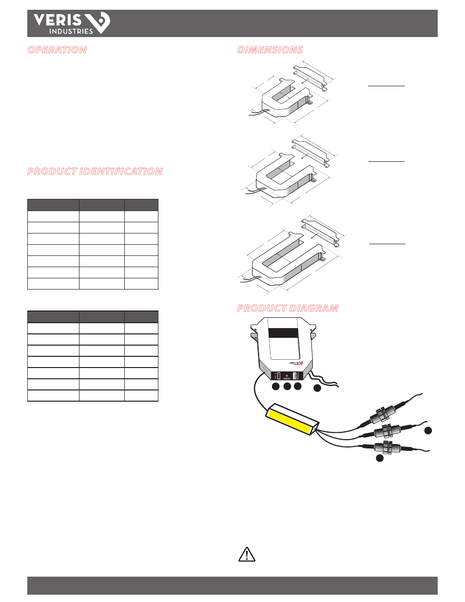
DIMENSIONS
Enercept
®
1
2
3
4
5
6
1. Voltage Leads
2. Fuses
3. Pulse Output connector
4. Status LED: blink codes: slow green for normal operation; slow red for incorrect
wiring or low power factor (less than 0.5); fast red for max. current exceeded.
5. Pulse Rate Switches: used to set the pulse output rate.
6. External CTs: permanently attached; do not disconnect or use with other power
meters.
Color match CTs and voltage leads! Example: clamp the red
labeled CT around the power conductor connected to the
red voltage wire.
A
B
E
F
C
D
B
E
F
C
D
A
A
B
E
C
F
D
SMALL
100/300 Amp
MEDIUM
400/800 Amp
LARGE
800/1600/2400 Amp
A =
3.8" (96 mm)
B =
1.2" (30 mm)
C =
1.3" (31 mm)
D =
1.2" (30 mm)
E =
4.0" (100 mm)
F =
4.8" (121 mm)
A =
4.9" (125 mm)
B =
2.9" (73 mm)
C =
2.5" (62 mm)
D =
1.2" (30 mm)
E =
5.2" (132 mm)
F =
6.0" (151 mm)
A =
4.9" (125 mm)
B =
5.5" (139 mm)
C =
2.5" (62 mm)
D =
1.2" (30 mm)
E =
7.9" (201 mm)
F =
6.0" (151 mm)