Veris Industries HP SERIES Install User Manual
Hp/hn, Notice, Digital rh and rh/t transmitters
TM
ENVIRONMENTAL SENSORS
INSTALLATION GUIDE
Z201381-0T
PAGE 1
©2013 Veris Industries USA 800.354.8556 or +1.503.598.4564 / [email protected]
03132
Alta Labs, Enercept, Enspector, Hawkeye, Trustat, Aerospond, Veris, and the Veris ‘V’ logo are trademarks or registered trademarks of Veris Industries, L.L.C. in the USA and/or other countries.
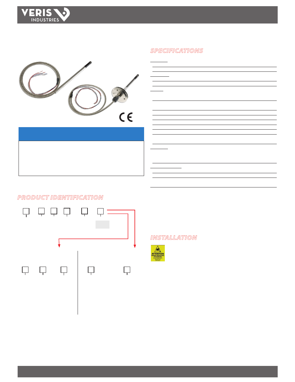
Digital RH and RH/T Transmitters
SPECIFICATIONS
Input Power: *
Voltage Models 12-30VDC/24VAC, 15mA max.
mA Model
loop powered 12-30VDC only, 30mA max.
Output Power:
Voltage Models
3-wire, observe polarity
mA Model
2-wire, not polarity sensitive (clipped and capped)
Humidity:
HS Element
Digitally profiled thin-film capacitive (32-bit mathematics)
U.S.
Patent No. 5,844,138
Accuracy @ 25°C from 10-80% RH**
±1%, ±2%, ±3%, or ±5% (specify);
Multi-point
calibration, NIST traceable
Reset Rate***
24 hours
Temperature Coefficient
+0.1% RH/°C above or below 25°C (typical)
Scaling
0-100%RH
Hysteresis
1.5% typical
Linearity
Included in Accuracy spec.
Stability
±1% @ 20°C (68°F) annually, for two years
Temperature:
Optional Temperature Transmitter Output
Digital, 4-20mA (clipped and capped) or
0-5V/0-10V output;
accuracy
to ±0.5°C (±1.0°F) typical
Operating Environment:
Operating Humidity Range
0 to 100% RH noncondensing
Operating Temperature Range
-40° to 50°C (-40° to 122°F)
Agency Approvals
EMC EN 50081-1, EN 50082-1, EN 61000-4-4, EN 61000-4-5,
EN
61000-4-3, ENV 50204, EN 61000-4-6
* One side of transformer secondary is connected to signal common. Isolation transformer or
dedicated power supply may be required.
** Specified accuracy with 24 VDC supplied power with rising humidity.
*** Reset Rate is the time required to recover to 50% RH after exposure to 90% RH for 24 hours.
RTD Thermistors are not compenstated for internal heating of product
To conform to EMC standards, shielded cabling and technical information is available from factory
upon request or is available on our website: www.veris.com
HP/HN
NOTICE
• This product is not intended for life or safety applications.
• Do not install this product in hazardous or classified locations.
• Read and understand the instructions before installing
this product.
• Turn off all power supplying equipment before working on it.
• The installer is responsible for conformance to all applicable codes.
No responsibility is assumed by Veris Industries for any consequences arising out of the
use of this material.
PRODUCT IDENTIFICATION
Available
HP
HN
T = Temp
X = No Temp
(Stop here)
US or EU
Temp.
Sensor Type
Accuracy NIST
S = Standard
C = CE
B = 100R Platinum, RTD
C = 1k Platinum, RTD
D = 10k T2, Thermistor
E = 2.2k, Thermistor
F = 3k, Thermistor
G = 10k CPC, Thermistor
H = 10k T3, Thermistor
J = 10k Dale, Thermistor
K = 10k with 11k shunt, Thermistor
M = 20k NTC, Thermistor
N = 1800 ohm TAC, Thermistor
Q = 1uA/˚C, Linitemp
R = 10k US, Thermistor
S = 10k 3A 221, Thermistor
T = 100k, Thermistor
U = 20k “D”, Thermistor
Output
M = 4-20mA
V = 0-5V/0-10VDC
1 = 1%
2 = 2%
3 = 3%
5 = 5%
H
Sensor Type Range
Temp Cert
Blank = None
1 =1pt Cal
2 = 2pt Cal
OPTION
Humidity Transmitter Combination
Humidity RTD/Thermistor Combination
Blank = None
1 =1pt Cal
2 = 2pt Cal
A
= Transmitter
N = NIST
X = None
Temp Cert
OPTION
1 = -40° to 50°C
(-40° to 122°F)
2 = 0° to 50°C
(32° to 122°F)
N = RH Insertion
P = RH Pendant
Enclosure
INSTALLATION
HP Pendant version:
1. Suspend the HP pendant sensor from the ceiling.
2. Wire the probe (see Wiring section).
HN Insertion version:
1. Drill a 5/8” mounting hole for the insertion probe into the monitored area surface.
2. Center the threaded insertion plate over the hole and drill mount.
3. Wire the probe (see Wiring section).
Observe precautions for handling static sensitive
devices to avoid damage to the circuitry that
is not covered under the factory warranty.