Power supply wiring, Data industrial – Badger Meter 340 BN/MB Btu Energy Transmitter User Manual
Page 9
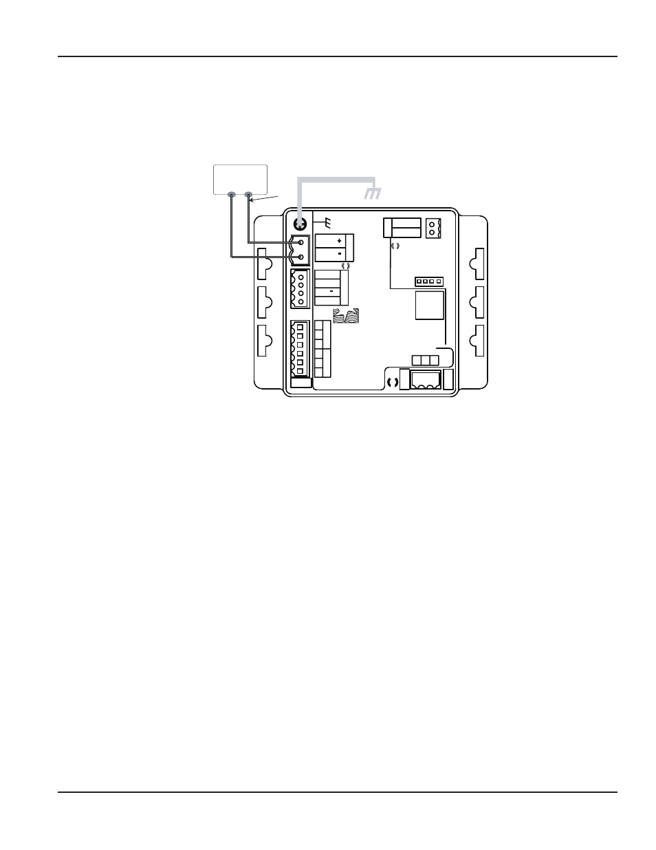
Power Supply Wiring
The 340 BN/MB Btu Energy Transmitter requires 12-24 Volts AC or DC to operate The power connections are made to the
ORANGE header The connections are labeled beside the header Observe the polarity shown on the label
If a Badger Meter plug-in type power supply (Series A-1026 or A-503) is used, connect the black/white striped wire to the
terminal marked positive (+) and the black wire to the terminal marked negative (–)
Comm LED
Data
Industrial
Shield
Signal
Signal +
Power Out
-
RE
F
+
_
D.
I.C.
Co
mm
Po
rt
+
-
Po
wer In
AC C /DC
AC L /DC
Output LED
Output
Pulse Out +
Pulse Out -
1
2
3
Temp
1
1
3
Temp
2
2
Input LED
DC +
or
AC Load
DC -
or
AC Common
Earth
Ground
AC or DC
Power Supply
Sensor Inpu
t
Model: 340
S/N 340-
XXXXXX
Figure 8: Sample Power Supply Wiring
NOTE:
N
Included with every 340 BN/MB Btu Energy Transmitter is a 340IK kit containing a screw, lock washer and nut to
connect the transmitter to earth ground Connect the earth ground lug of the 340 BN/MB Btu Energy Transmitter to
a solid earth ground with as short a wire as possible This will help prevent electrical interference from affecting the
transmitter’s normal operation
Installation & Operation Manual
Page 9
July 2012