Connecting the rs-485 buss – Badger Meter 340 BN/MB Btu Energy Transmitter User Manual
Page 12
+
-
Po
wer In
AC C /DC
AC L /DC
Output LED
Output
Pulse Out +
Pulse Out -
Pulse Input
NOTE:
maximum sinking current
is 100 mA @ 36 VDC
Device
(-) (+)
Figure 12: Sample Pulse Output Wiring Diagram
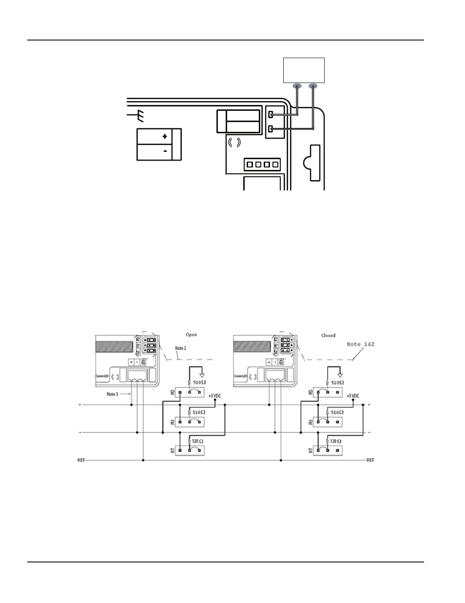
Connecting the RS-485 Buss
As shown in the Sample Pulse Output Wiring Diagram, the position of jumpers on each 340 BN/MB Btu Energy Transmitter
and wiring between each transmitter and the RS-485 network are different depending on where the transmitter is installed,
that is, its nodal position For all but the final transmitter in a string, the three jumpers NT, PU and PD should be in the open
position, and only the (+) and (–) network terminals should be connected to the RS-485 buss For the final 340 BN/MB Btu
Energy Transmitter in a Modbus network, the three jumpers NT, PU and PD should be in the closed position, and all three
network terminals, (+), (–) and REF, should be connected to the Modbus buss
NOTE:
N
The 340 BN/MB Btu Energy Transmitter default Modbus or BACnet polling address must be changed before it is
introduced into an existing network to avoid possible address conflicts Please refer to programming instructions in
the previous section
Figure 13: Sample Wiring Diagram to Modbus Network
NOTE 1: Biasing, circuitry and resistors for PU, PD and NT terminals are integral parts of the 340 BN/MB Btu Energy
Transmitter
NOTE 2: For the final 340 BN/MB Btu Energy Transmitter in a given RS-485 network string, NT, PU and PD jumpers should be
in the closed position Otherwise, NT, PU and PD should be in the open position
NOTE 3: For the final 340 BN/MB Btu Energy Transmitter in an RS-485 string, all three network terminals, (+), (-) and REF,
should be connected to the buss Otherwise, connect only terminals (+) and (-) to the buss
Data Industrial® 340 BN/MB BTU Energy Transmitter
Page 12
July 2012