Sensor wiring, Series 200, Sdi series – Badger Meter 340 BN/MB Btu Energy Transmitter User Manual
Page 10: Other flow sensors
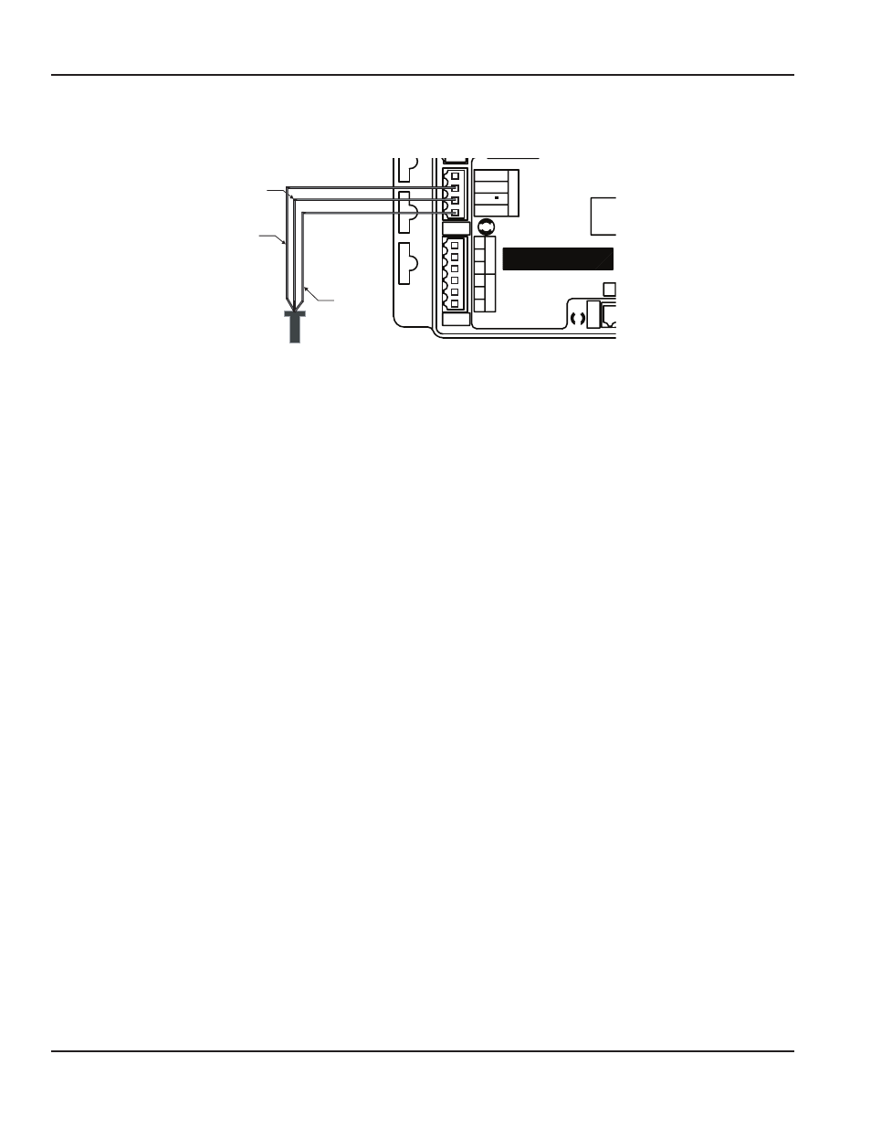
Sensor Wiring
All flow sensor types connect to the four terminal headers labeled “Sensor Input ”
Comm LED
Sensor Inpu
t
Shield
Signal
Signal +
Power Out
-
RE
F
+
_
Fa
ct
or
y Po
rt
NT
PD
PU
D.I.C.
Comm
Port
+
-
Po
wer In
AC C /DC
AC L /DC
Output
Pulse Out +
Pulse Out -
1
2
3
Temp
1
1
3
Temp
2
2
Input LED
Red
or Signal +
Black
or Signal -
Shield
(if applicable)
Series 200
or SDI Sensor
Model: 340
S/N 340-
XXXXXX
Figure 9: Sample Sensor Wiring Diagram
Series 200
Connect the red wire to sensor signal (+), black wire to sensor signal (–) and the bare wire to shield
SDI Series
Connect the plus (+) terminal of the sensor to sensor signal (+) on the transmitter and the minus (–) terminal of the sensor to
sensor signal (–) on the transmitter Connect the shield terminal of the sensor to the shield terminal of the transmitter
Other Flow Sensors
The sensor input power out terminal supplies nominal 12V DC excitation voltage for three-wire sensors Connect sensor signal
(+) and sensor signal (–) wires to transmitter terminals
The 340 BN/MB Btu Energy Transmitter is very versatile and can accept both pulse and zero crossing sine wave flow sensors
Excitation voltage is also provided for three-wire powered sensors (Example: hall effect, of Badger Meter Series 4000)
See the Programming section
for configuration instructions
Data Industrial® 340 BN/MB BTU Energy Transmitter
Page 10
July 2012