Temperature element wiring, Thermistors, Resistance temperature detectors (rtds) – Badger Meter 340 BN/MB Btu Energy Transmitter User Manual
Page 11: Pulse output wiring
Temperature Element Wiring
Appropriate wire types and proper shielding is required for accurate temperature readings
Since Btu calculations are based on Delta T cable, in order to maintain a balanced system, T1 and T2 wire runs should be kept
to approximately the same length, not to exceed 500 feet
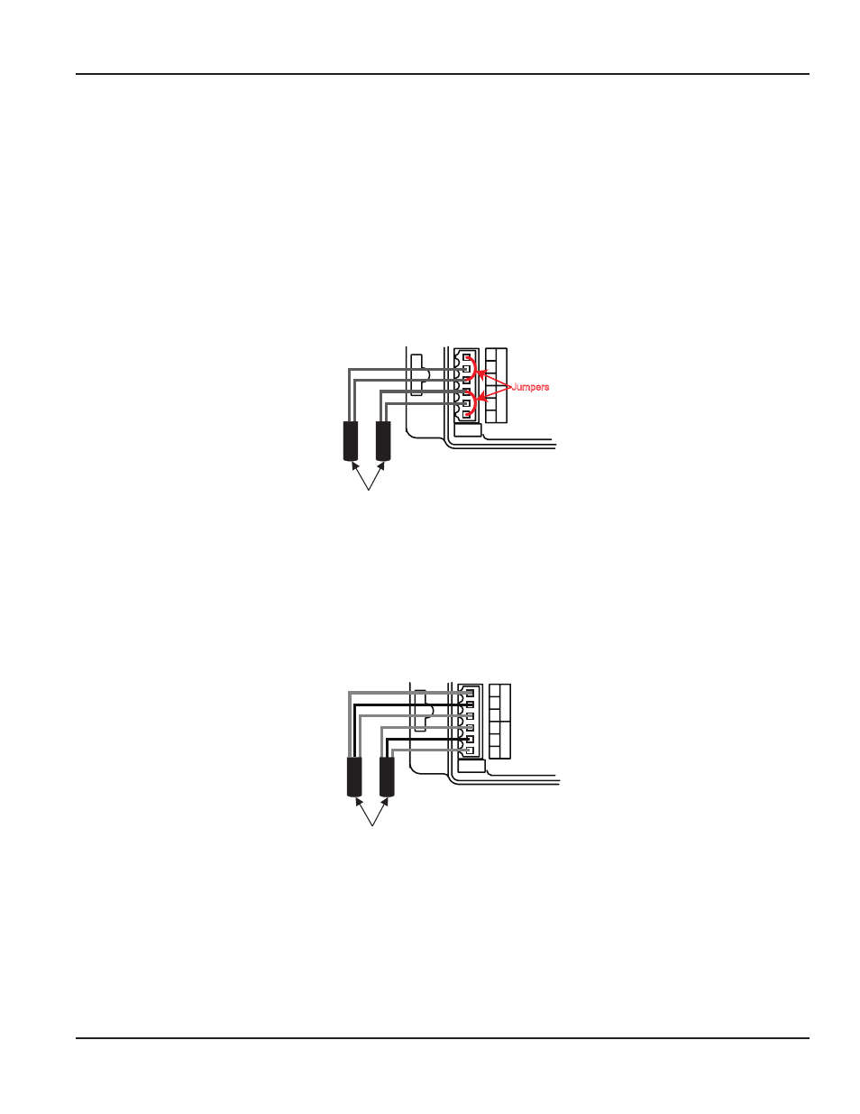
Thermistors
Badger Meter thermistors are not polarity-sensitive, therefore, wire color is unimportant The thermistor located in the same
pipe as the flow sensor, termed temperature sensor T1, should be connected to terminals 2 and 3 on terminal block
Temp 1 The thermistor located in the other pipe, termed temperature sensor T2, should be connected to terminals 2 and 3 on
terminal block Temp 2 As shown in the thermistor wiring diagram (Figure 10), a jumper must be installed between terminals
1 and 3 for both the T1 and T2 input terminals These terminals 1 and 3 are used for lead resistance compensation when 100
three-wire RTDs are used and must be jumpered when not used
1
2
3
Temp
1
1
3
Temp
2
2
10KΩ
T2
T1
Supply
Return
Thermistors
Jumpers
Figure 10: Thermistor Wiring Diagram
Resistance Temperature Detectors (RTDs)
Badger Meter RTDs are three-wire devices Two of the wires are the same color and interchangeable One wire is
current-carrying and connects to terminal #3, and the other is used for lead compensation and is connected to terminal #1
The single color lead is attached to terminal 2 The RTD located in the same pipe as the flow sensor, temperature sensor T1,
should be connected to terminal block Temp 1 The RTD located in the other pipe line, temperature sensor T2, should be
connected to terminal block Temp 2
1
2
3
Temp
1
1
3
Temp
2
2
100Ω RTDs or 1000Ω RTDs
T2
T1
Suppl
y
Retur
n
Figure 11: RTD Wiring Diagram
Pulse Output Wiring
The 340 BN/MB Btu Energy Transmitter has solid-state switch output rated for a maximum sinking current of 100 mA at 36V
DC In most cases the pulse out (+) terminal of the 340 BN/MB Btu Energy Transmitter will connect to the input pulse (+) and
the pulse out (–) terminal to the input pulse (–) of the receiving device Although labeled +/–, the pulse output is not actually
polarity sensitive and can switch low level AC loads if required
These terminals are located on a separate two-terminal removable header on the 340 BN/MB Btu Energy Transmitter, labeled
“Output ”
Installation & Operation Manual
Page 11
July 2012