Communications cable wiring, Data industrial, Figure 14: location of the dic com port – Badger Meter 340 BN/MB Btu Energy Transmitter User Manual
Page 13
Connection to the RS-485 network should not be made until the 340 BN/MB Btu Energy Transmitter has been configured per
the instructions in "Programming" on
See RS-485 Network Configuration on
Communications Cable Wiring
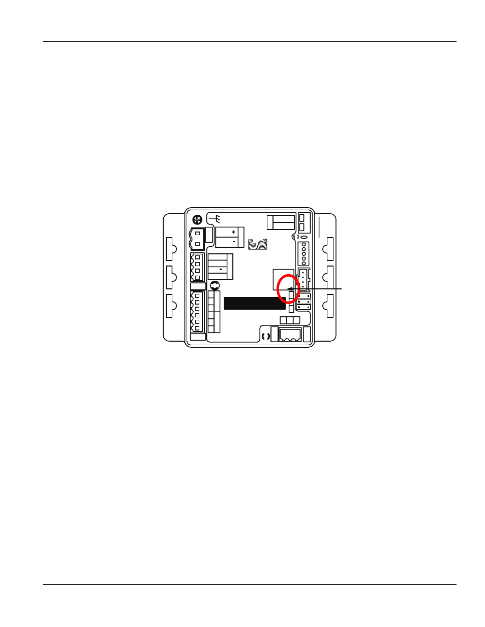
Field configuration requires a Data Industrial programming kit (consisting of a custom cable and software) and a PC running
Windows 9x, ME, NT, 2000 or Windows 7 In order to connect, the 340 BN/MB Btu Energy Transmitter must be powered, and
the Data Industrial Series A301 cable must be connected to the 340 BN/MB Btu Energy Transmitter COM port connector and
an available 9-pin COM port on a computer USB to COM Port adapters can be used if the DB9 COM port is not available
NOTE:
N
The Data Industrial A301 Cable will work with all Series 300 products However the older version of the cable (A300)
does not have sufficient bandwidth to work with the 340 BN/MB Btu Energy Transmitters
Badger Meter provides free programming software updates via the Internet for all Series 300 products Go to
www badgermeter com Software updates can be found in the Industrial/Impeller/Transmitter section
Model: 340 BN/MB
S/N 340-
005100
Comm LED
Data
Industrial
Sensor Inpu
t
Shield
Signal
Signal +
Power Out
-
RE
F
+
_
Btu ENERGY METER
Fa
ct
or
y Po
rt
NT
PD
PU
D.I.C.
Comm
Port
+
-
Po
wer In
AC C /DC
AC L /DC
Output LED
Output
Pulse Out +
Pulse Out -
1
2
3
Temp
1
1
3
Temp
2
2
Input LED
Figure 14: Location of the DIC COM Port
D I C Comm Port
DIC COM Port
Installation & Operation Manual
Page 13
July 2012