Installation guide, Operation, Wiring & configuration – Veris Industries PX SERIES Install User Manual
Page 3: Px series, Range selection guide
Z205213-0D
PAGE 3
©2012 Veris Industries USA 800.354.8556 or +1.503.598.4564 / [email protected]
07122
Alta Labs, Enercept, Enspector, Hawkeye, Trustat, Veris, and the Veris ‘V’ logo are trademarks or registered trademarks of Veris Industries, L.L.C. in the USA and/or other countries.
TM
PX SEriES
inStallation GUiDE
oPeration
PX Series devices employ ceramic capacitive sensors and sophisticated temperature
compensation circuitry. The sensor achieves its best accuracy after an initial warm-up
period. During the first few minutes of operation, readings at zero pressure and the
lowest pressure ranges appear erroneous. Following this initial warm-up period, PX
Series maintains its specified accuracy and stability.
LCD DISPLAY: The display momentarily indicates range “SET” when selection is made.
Pressure is normally indicated on the display. Units are in inches water column (in. W.C.),
Pascals (Pa) or kilopascals (kPa) as indicated on the display. The display shows OVER
when the pressure is over range.
ZERO: Press and hold the ZERO pushbutton for 2 seconds or provide contact closure
on ‘AUX ZERO’ terminal to automatically reset the output and display to zero
pressure. To protect the unit from accidental zero, this feature is enabled only when
the detected pressure is within about 0.1 in. W.C. (25 Pa) of factory calibration.
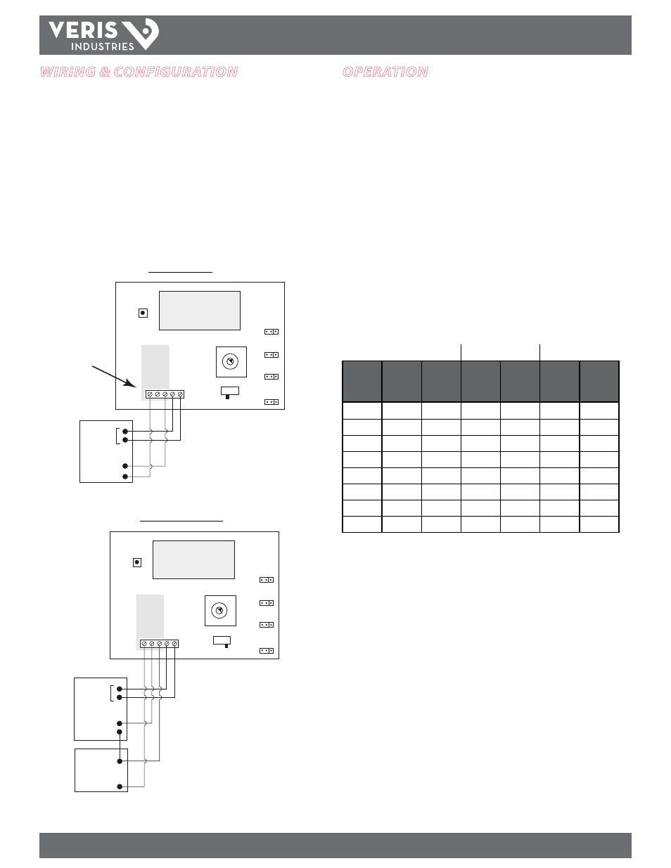
WirinG & confiGuration
Connect the transmitter to the control system and power supply as indicated below.
Optional: Connect the ZERO terminals to the digital output (contact closure) of the
control system.
Use the switch to select voltage (V) or current (mA) mode.
Jumper JP4: select 0-10 V or 0-5 V output span (voltage mode only).
Jumper JP5: select bidirectional or unidirectional mode.
Jumper JP7: select inches W.C. or Pascal scale
Jumper JP8: select fast or standard response time.
Align the arrow (not the slot) on the rotary switch to the desired full-scale range. LCD
models momentarily indicate the selected range.
PO
WER (4-20mA
)
OUT (0-10v)
COM ZERO
Volt
OUTPUT
mA
ZERO
DIGITAL CONTROL
Digital
Output
V IN
-
POWER SOURCE
24VAC/DC
-
+
1.000
VOLT
5V/10V
JP4
MODE
BI/UNI
JP5
RESPONSE
FAST/STD
UNITS
IN W.C./PA
JP7
JP8
0 1
2
3 4
5
6
7
3-wire, 0-5 V/0-10 V
2-wire, 4-20 mA
PO
WER (4-20mA
)
OUT (0-10v)
CO
M
ZERO
Volt
VOLT
OUTPUT
mA
5V/10V
JP4
MODE
BI/UNI
JP5
ZERO
DIGITAL CONTROL
Digital
Output
Return
V+
1.000
WARNING:
Do not
apply power
to output terminal!
Permanent damage
will result.
RESPONSE
FAST/STD
UNITS
IN W.C./PA
JP7
JP8
0 1
2
3 4
5
6
7
Range Selection Guide
PX01
PX02
PX05
Rotary
Switch
Position
Inches
W.C.
Pascal
Inches
W.C.
Pascal
Inches
W.C.
Pascal
0
0.1
25
1
250
0.1
25
1
0.25
50
1
250
0.25
50
2
0.5
100
1
250
0.5
100
3
1
250
1
250
1
250
4
1
250
2.5
0.5 kPa
2.5
0.5 kPa
5
1
250
5
1 kPa
5
1 kPa
6
1
250
10
2.5 kPa
10
2.5 kPa
7
1
250
10
2.5 kPa
10
2.5 kPa