Installation guide, Configuration, Rs-485 communications setup – Veris Industries H8186-CB Install User Manual
Page 3
Z204062-0F
PAGE 3
©2012 Veris Industries USA 800.354.8556 or +1.503.598.4564 / [email protected]
02122
Alta Labs, Enercept, Enspector, Hawkeye, Trustat, Veris, and the Veris ‘V’ logo are trademarks or registered trademarks of Veris Industries, L.L.C. in the USA and/or other countries.
TM
Power MoNITorING
INSTALLATIoN GUIDe
configuration
This section describes the communications settings you must make to the H8186-CB.
When daisy-chaining devices, follow these guidelines:
• Connect up to 63 H8186-CB devices on a single daisy chain.
• Each H8186-CB device on the daisy chain must have a unique address.
Before connecting the H8186-CB to the RS-485 communication wires,
set the address according to directions in “Selecting the Network Address
DIP Switches” on this page. If you assign the same address to two devices,
neither device will communicate.
• Set the baud rate according to directions in “Selecting Baud Rate —
Communication DIP Switches.” The settings for each H8186-CB must
match the other devices on its daisy chain.
• For RS-485 cables, use shielded, twisted-pair wire (Belden Cable 1120A or
equivalent).
• If the H8186-CB is the last device, terminate it per the RS-485 standard
(120 Ω nominal impedence).
Selecting The Network Address DIP Switches
Use the Network Address DIP switches to select the network address. Each H8186-CB
on a daisy chain must have a unique network address (from 0 to 63). Devices with the
same address will be unable to communicate.
Always set the address before you install the H8186-CB in the energy meter and
before you connect the energy meter to the daisy chain.
Each of the six DIP switches has a unique address value, page 6 lists DIP switch
positions for specific addresses.
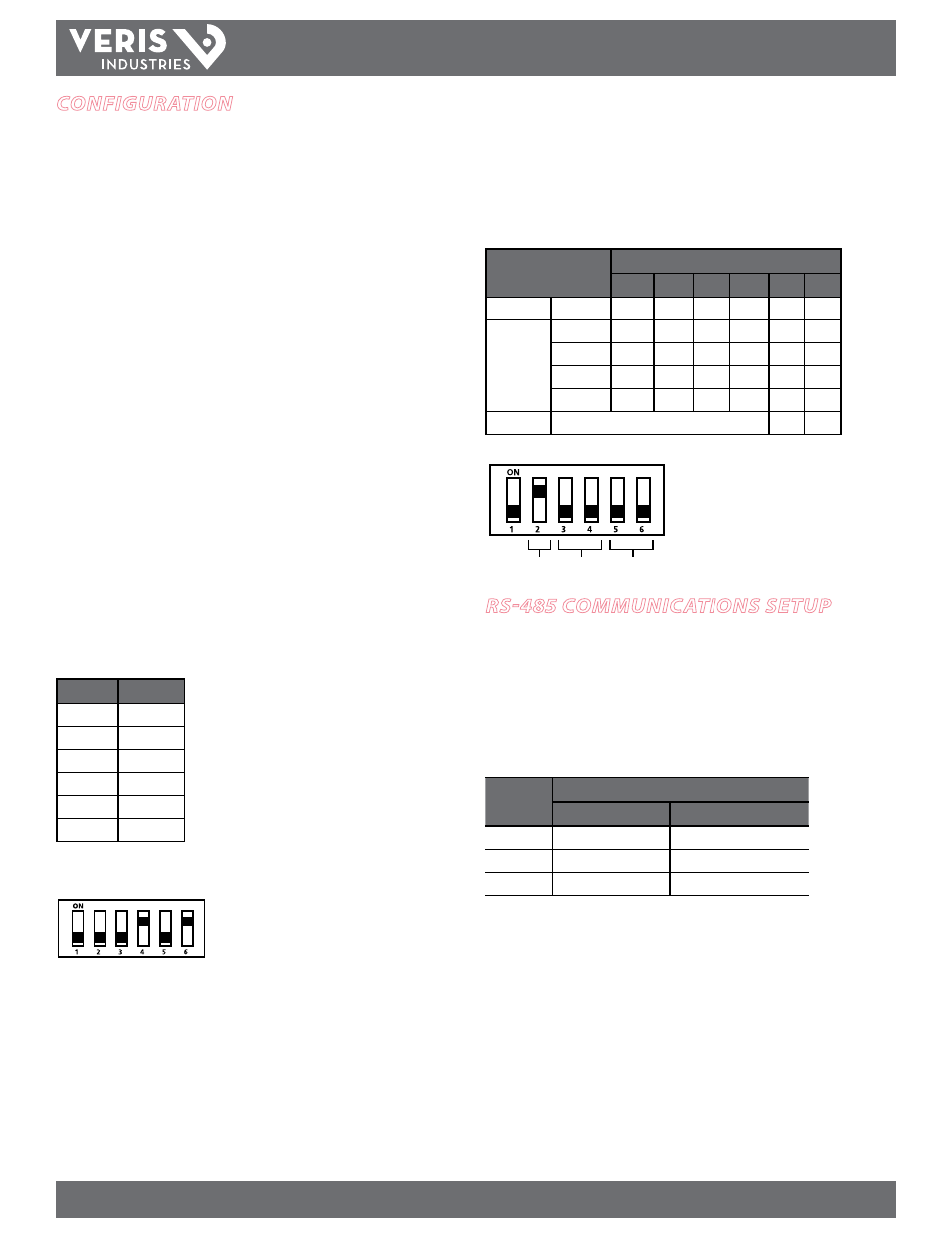
Network Address DIP Switch Values
Switch
Value
1
1
2
2
3
4
4
8
5
16
6
32
8 + 32 = 40
In this example, the network address for the device
is 40. Switch 4 and 6 offer the only combination of
values that total 40.
This figure illustrates how to set the switches. Up is
ON; down is OFF.
Selecting Baud Rate – Communication DIP Switches
Use the communication DIP switches (pictured below) to set the H8186-CB baud rate.
The figures below list the baud rate switch settings and the location of these
switches.
Wiring and Baud Rate Settings
Parameter
Switch Number and Setting
1
2
3
4
5
6
Wire Type
2-wire
–
ON
Baud Rate
9600
–
OFF
OFF
19200
–
ON
OFF
38400
–
OFF
ON
38400
–
ON
ON
Parity
Not applicable to this model.
OFF
OFF
Switches 1, 5, and 6 are unused. Always leave
them in the OFF position.
This example illustrates the default switch
settings for a 2-wire device that uses 9600
baud rate.
Parity function is not applicable to this model;
leave these switches in the OFF position.
Wiring Baud
Parity
rs-485 communications setuP
Daisy Chain Maximum Distances
The maximum number of devices capable of being supported on a single daisy chain
is determined based on the combination of baud rate, the length of the daisy chain,
and the types of RS-485 devices on the daisy chain. The RS-485 interface will support
daisy chains that fall within the specifications shown below.
2-Wire Daisy Chain Maximum Distances
Baud Rate
Maximum Distances
1-8 Devices
9-16 Devices
9600
10000 ft. (3048 m)
4000 ft. (1219 m)
19200
5000 ft. (1,524 m)
2500 ft. (762 m)
38400
2500 ft. (762 m)
1200 ft. (380 m)
Wiring the Connector
Remove the connector from the RS-485 communication terminals of the H8186-CB
(see Wiring Diagram section). To wire RS-485 communications, follow these steps:
1. Wire the communications connector for 2-wire communication (see Wiring
Diagram section). The Wire Type setting in the communication DIP switch must
match this wiring type (set Switch 2 to the ON position; see Selecting Baud Rate
section).
2. Use a small, flat-blade screwdriver to tighten the connector screws.
3. Replace the connector on the RS-485 communication terminals of the H8186-CB.
4. If the H8186-CB is the last device on the daisy chain, terminate it to ensure reliable
communication per the RS-485 standard (120 Ω nominal impedence).