Chapter 2: connections & settings, 1 ldra6 board – Veris Industries LDRA6 USER GUIDE User Manual
Page 10
Chapter 2: Product Overview
User Guide: LDRA6
www.rletech.com 970
484-6510
4
CHAPTER 2: CONNECTIONS & SETTINGS
2-1
LDRA6 BOARD
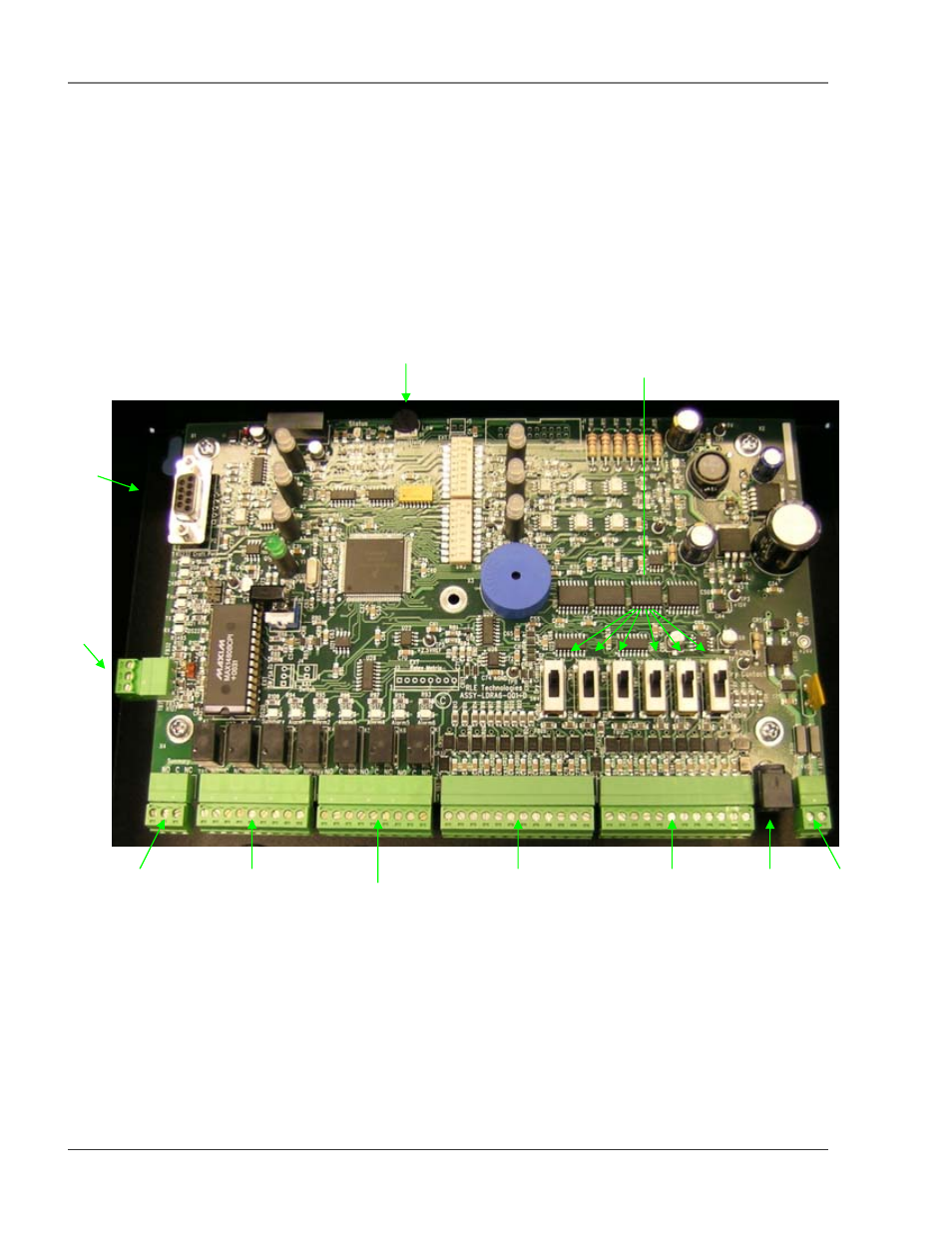
The LDRA6’s zone connectors, labeled TB2, are found at the bottom of the board on the double-stacked
terminal block. The switches on the board are labeled SW1 and SW2. The unit has one dial, labeled R1,
which is used to manually adjust the sensitivity for all zones. Sensitivity for individual zones may be
configured through the LDRA6’s RS232 Craft Port configuration, labeled P2. The switches for
configuring Dry Contact or Leak Detection monitoring for zones are labeled SW4 through SW9.
Figure 2-1: LDRA6 Board
R1
Leak Sensitivit
y
TB1
Power
POW1
Power
TB2
Zone
TB3
Zone
TB4
Zone
Alarm
Relays
TB5
Zone
Alarm
Relays
TB6
Summary
Relay
TB7
RS485
P2
RS232
SW4 – SW9
Zone
Configuration
- E8950 Datasheet (2 pages)
- HWS SERIES Datasheet (2 pages)
- H721LC Install (2 pages)
- VST11 (-4) Install (2 pages)
- V120 Datasheet (2 pages)
- VMD4B-C SERIES Datasheet (2 pages)
- E51C3 Install (34 pages)
- V202 Install (2 pages)
- HW SerieS Install (2 pages)
- T SERIES Datasheet (2 pages)
- FSRxxxx SERIES Install (59 pages)
- H931 Install (4 pages)
- VT76xxB SERIES Datasheet (2 pages)
- H11D Install (3 pages)
- H939 Install (2 pages)
- PXR SERIES Install (3 pages)
- HS Install (2 pages)
- V102 Install (2 pages)
- A8332–8F2D Datasheet (2 pages)
- 196 Manual (23 pages)
- HEW SEriES Datasheet (2 pages)
- H8186-CB Install (8 pages)
- H931 Datasheet (2 pages)
- H970LCA Install (2 pages)
- H663 SERIES Datasheet (2 pages)
- E3X Commissioning Guide (18 pages)
- TJ SERIES Datasheet (2 pages)
- E50H5A Install (28 pages)
- H308 Install (2 pages)
- H904 Install (2 pages)
- H8822 Install (22 pages)
- AE011 Datasheet (1 page)
- H84xx Install (29 pages)
- PVE SERIES Install (2 pages)
- H932 Install (3 pages)
- H809 Install (2 pages)
- H948 Install (2 pages)
- V221 Install (2 pages)
- E5x SERIES Datasheet (2 pages)
- H540 Install Install (4 pages)
- V200 SERIES Install (2 pages)
- V421 Install (2 pages)
- H958 Install (2 pages)
- TW SERIES Install (3 pages)