Pinion position, Pinion assembly – Spicer Tandem Drive Axles Service Manual J340-S, J380-S, J400-S, W460-S User Manual
Page 21
FFFFFigur
igur
igur
igur
igure 1
e 1
e 1
e 1
e 13
3
3
3
3
PINION POSITION
19
Ring gears and pinions are supplied in matched sets only.
Matching numbers on both the pinion and ring gear are etched
for verification. If a new gear set is being used, verify the
numbers of each pinion and ring gear before proceeding with
assembly. (See Gear Set Identification, Pg. 2)
Pinion position is based on the nominal mounting distance
measured from the centerline of the ring gear to the nose of
the pinion. This dimension is controlled by selectively
shimming between the pinion cage assembly and the carrier
housing. The nominal dimension is 3.976 in. (100.990 mm).
NOTE: Be sure mounting surfaces and shims are free of burrs
and dirt prior to assembly as they will affect pinion position.
1 . To establish the correct nominal dimension by using a
pinion setting gauge, install pinion and cage assembly
into the carrier housing without shims. Tighten pinion
cage bolts to correct torque specifications. (See Torque
Specification Chart, Pgs. 33-34) Failure to tighten
properly may result in incorrect gear adjustment.
2 . Attach the step plate clamp assembly to the carrier
mounting flange. Locate step plate clamp screw over
center of pinion. Install step plate under clamp screw and
tighten to hold step plate securely in position.
NOTE: Be sure lugs on bottom of step plate straddle the
bearing staking indentions on end of pinion, or false reading
may occur. Also, make sure differential side bearing bores
are clean and free of nicks.
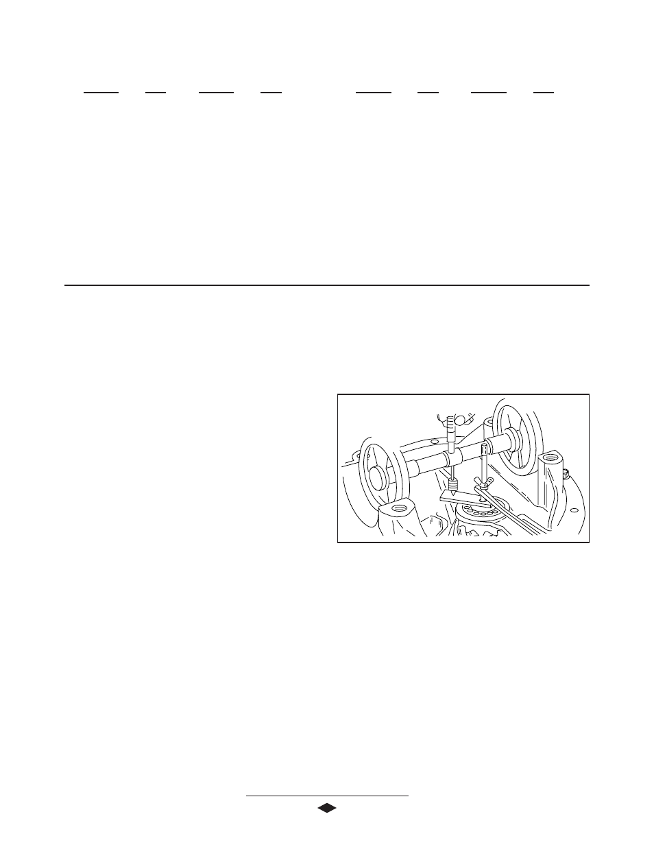
3 . Remove any burrs and wipe clean differential bearing
bore I.D.'s. Turn micrometer 90º to step plate. Install
assembled pinion setting gauge into bearing bores of
carrier housing until fully seated. Adjust micrometer so it
is directly over end of step plate. Run the micrometer
thimble down to measure the distance between the center
of the ring gear and the step plate. Make a note of this
dimension. See Figure 13.
NOTE: Because the step plate must be taken into consider-
ation, the thickness of the step plate (.400 in. (10.16 mm))
needs to be added to the measured value for the correct
micrometer distance.
4 . On the machined end of each pinion either a plus (+),
minus (-), or a zero (0) will be etched. (See Gear Set
Identification, Pg. 2) This number represents the amount
J Model
W Model
Inches
M M
Inches
M M
.720
18.29
.895
22.73
.721
18.31
.896
22.76
.722
18.34
.897
22.78
.723
18.36
.898
22.81
.724
18.39
.899
22.84
.725
18.41
.900
22.86
.726
18.44
.901
22.89
.727
18.47
.902
22.91
.728
18.49
.903
22.94
.729
18.52
.904
22.96
.730
18.54
.905
22.99
.731
18.57
.906
23.01
J Model
W Model
Inches
M M
Inches
M M
.732
18.60
.907
23.04
.733
18.62
.908
23.06
.734
18.64
.909
23.09
.735
18.67
.910
23.11
.736
18.69
.911
23.14
.737
18.72
.916
23.27
.738
18.75
.739
18.77
.740
18.80
.741
18.82
.742
18.85
.745
18.92
PINION ASSEMBLY