Pinion disassembly – Spicer Tandem Drive Axles Service Manual J340-S, J380-S, J400-S, W460-S User Manual
Page 16
PINION DISASSEMBLY
1 . Remove pinion bearing cage mounting bolts.
2 . Remove pinion bearing cage and cage assembly from
carrier housing. If difficulty is encountered in removing
pinion assembly from carrier, place a brass drift on inner
end of pinion and tap lightly.
NOTE: Retain shims for possible use during reassembly.
3 . Mount pinion assembly in a soft jawed vise or fixture,
holding yoke or pinion stationary. Remove roll pin, nut,
and washer.
4 . Remove the end yoke or drive gear using a suitable press.
5 . Remove pinion from cage assembly.
6 . Located between pinion bearings is a selective spacer,
used for pinion bearing preload. Retain this spacer for
possible use in reassembly.
7. Lift out the outer pinion bearing cone.
8 . Remove inner pinion bearing cup, using a suitable
adapter and press or puller.
9 . Remove roller bearing from end of pinion.
10 .Remove inner bearing cone from pinion.
Pinion Disassembly Complete
14
Used in place of
pinion driven gear,
castillated pinion
nut,and roll pin, that
are used on the
forward rear axle
carrier assembly.
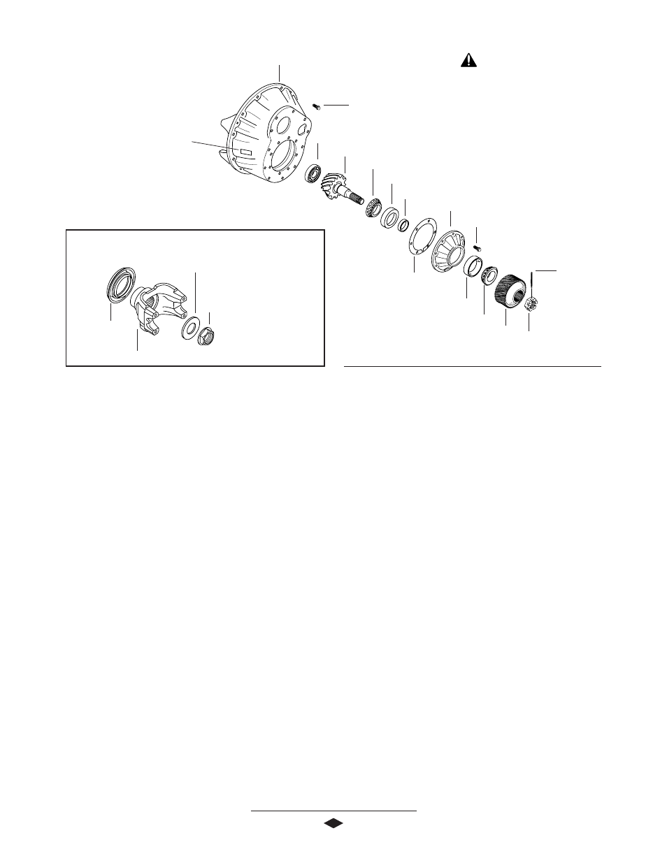
REAR REAR AXLE COMPONENTS
Washer
Pinion Nut
End Yoke
Pinion Seal
Carrier Housing
Pinion Pilot Bearing
Pinion
Inner Pinion Bearing Cone
Inner Pinion Bearing Cup
Pinion Bearing Cage
Outer Pinion Bearing Cup
Outer Pinion Bearing Cone
Pinion Bearing Cage Bolt
(115-135 Lb-Ft)
(156-183 N-m)
Bearing Preload Spacer (Selective)
Carrier Mounting Bolt
(240-260 Lb-Ft)
(325-352 N-m)
Castillated Pinion Nut
(600- Lb-Ft)Min.
(217 N-m) Min.
Pinion Position Shim(s)
Pinion Driven Gear
Roll Pin
ID Tag
IMPORTANT: Torque
specifications, shown on illustration,
apply only to J Model. See Page 33-
34 for W Model torque specifications.