MSD 2910 Atomic EFI Master Kit Installation User Manual
Page 9
INSTALLATION INSTRUCTIONS
9
M S D
• W W W . A T O M I C E F I . C O M • ( 9 1 5 ) 8 5 5 - 7 1 2 3 • F A X ( 9 1 5 ) 8 5 7 - 3 3 4 4
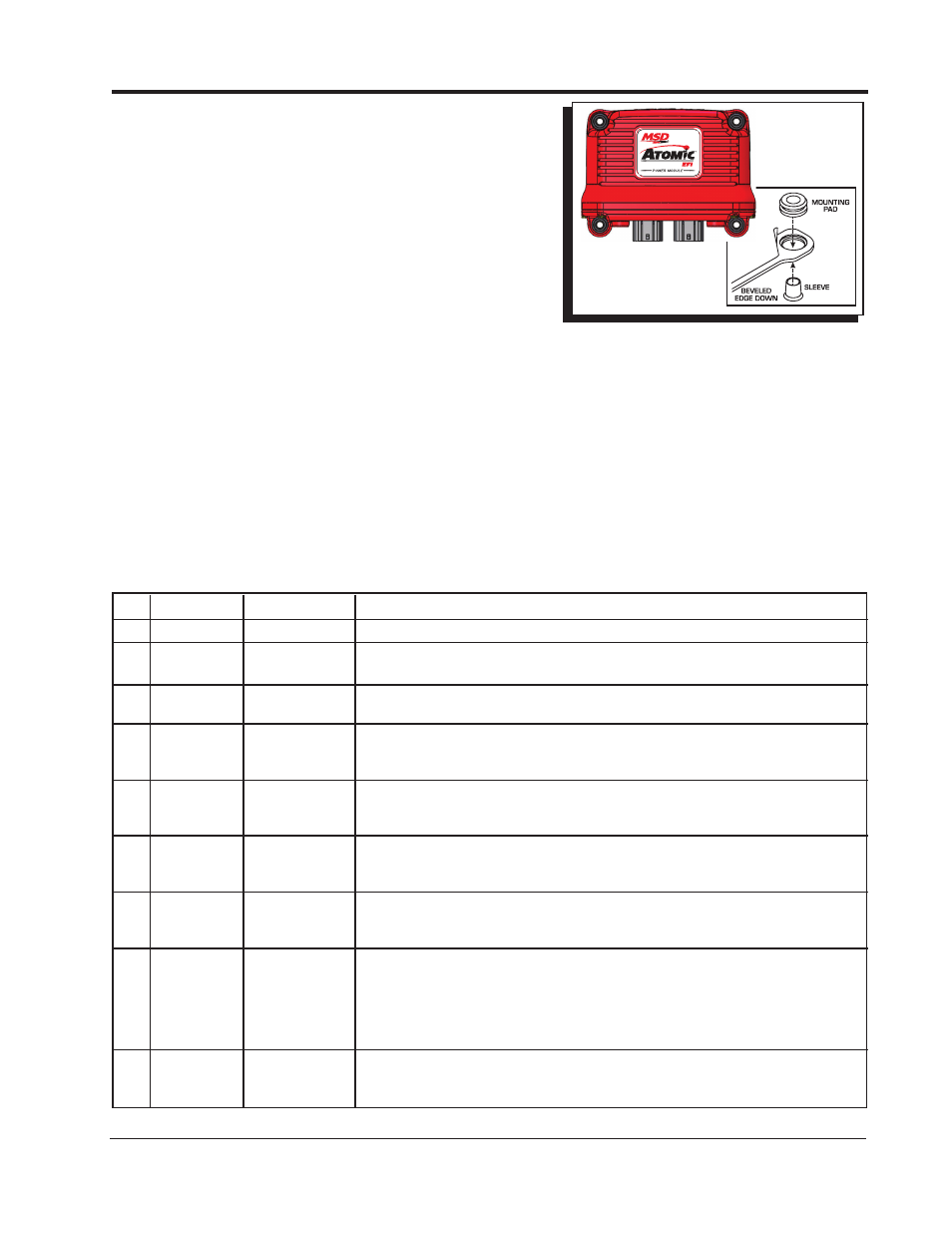
POWER MODULE INSTALLATION
The Power Module of the Atomic EFI system handles high
current circuits such as the fuel pump and WBO2. The unit
has two ports for the MSD CAN system as well as a wiring
harness. The CAN ports will provide communication between
the Power Module, Throttle Body, and Handheld Controller.
It is important to select a proper mounting location for the
Power Module. The unit can be mounted in the interior or
the engine compartment as long as it is away from direct
heat sources. It is not recommended to mount the unit in an
enclosed area, such as the glove box, so that airflow will aid
in cooling. When a suitable location is found to mount the
Module, make sure all wires reach their connections. Also
be sure that the CAN ports can be accessed for use of the
Handheld. Use the Power Module as a template and mark the location of the holes. Use a size # 20 drill bit
to prepare for the supplied self tapping screws. Install the supplied rubber gromments and mount the unit.
Figure 8 Power Module Wiring Diagram.
WIRING
There are a number of electrical connections on the Power Module that are required for proper operation.
Other wires, such as fan control wires, only need to be connected if their optional functions are being
used. Wires marked “REQ” must be connected for the system to operate while those marked “OPT”
will depend on the functionality desired. Note that the two schematics shown are for installations that
are NOT using the timing functions of the Atomic. At this point it is recommended to start the system
without including the ignition wiring to confirm and tune-in the Atomic for your installation. If you wish to
proceed with timing installation, follow the wiring below, and contiune to page 16 to set up the distributor
and ignition timing.
Pin REQ. / OPT. Wire Color
Description
1
REQ
Black
Ground - Route this wire directly to Battery Negative or the engine block.
2
OPTIONAL
Tan
Fan circuit 1 - This wire supplies ground to activate the circuit. It must go to
the ground circuit of a relay to control a fan.
3
OPTIONAL
Pink
Fan circuit 2 - This wire supplies ground to activate the circuit. It must go to
the ground circuit of a relay to control a fan.
4
Unused
(No Wire)
Unused
5
Unused
(No Wire)
Unused
6
Unused
(No Wire)
Unused
7
Optional
Violet
Nitrous Signal - When connected to 12 volts, such as when nitrous is activated,
the Atomic will switch to the target air/fuel mixture for use during nitrous. The
timing will also be retarded the programmed rate (when timing control is used).
8
REQ
Orange (Large) Fuel Pump circuit - This wire provides 12 volts to the fuel pump and connects
to the positive side terminal. No relay is required. Note that on a returnless
style fuel system the voltage on this wire will not display on a voltmeter.
9
REQ
Red (Large)
Main Power - Route this wire directly to Battery Positive. This circuit needs to
maintain power after the unit is turned off so that all Learning can be saved
properly.
10
REQ
Red
Wide Band Oxygen Sensor connection - single connector.
11
Yellow
12
Black / White
13
Black / Red
14
Green
15
Black
16
REQ
Red
On/Off – Connect to a switched 12 volt circuit. Ensure it has power during both
Key On and Cranking. Do
NOT connect the coil (+) terminal when using an
MSD Ignition such as a 6A or 6AL or other CD ignition.