MSD 2910 Atomic EFI Master Kit Installation User Manual
Page 8
8
INSTALLATION INSTRUCTIONS
M S D
• W W W . M S D P E R F O R M A N C E . C O M • ( 9 1 5 ) 8 5 5 - 7 1 2 3 • F A X ( 9 1 5 ) 8 5 7 - 3 3 4 4
PUSH-LOCK FITTING INSTALLATION
MSD supplies two fitting adapters that will accept a
-6 AN line to be connected. If you are using the MSD
Push-Lock fittings to connect the fuel hose, the supplied
hose MUST be used.
Proper installation begins with a clean, square cut of
the hose. A hose cutting tool or new razor blade are
recommended. When installing the hose it is important
that the hose is pushed on all the way to the thin beauty
ring. This means the hose should fully overlap the
inboard barb. Too little of engagement, as well as over-
engagement, will result in a compromised connection that
is prone to failure. Figures 6 and 7 illustrate the required
installation of the hose and fittings.
1. Determine the length of hose needed. Mark the hose
and cut it using a hose cutter or new razor blade.
There should be minimal disturbance of the outer
jacket, braids and inner liner. The cut plane should
be perpendicular to the hose axis. (Figure 5).
2. Before installing the hose to the fitting, it is important to
anchor the fitting (Figure 6). Proper installation cannot
be achieved by holding the hose and fitting in your
hands. For best results, the hose should be installed
with minimal twisting or pausing.
3. Apply a light coat of oil to the barbs on the fitting. Use
care not to get oil on the outside of the hose as it will
be impossible get a firm grip on the hose.
4. With the fitting anchored securely, push the hose
over the barbs. The hose is properly installed when
it is flush with the thin edge of the beauty ring (Figure
7). At this point, the hose end should have rolled over
the inboard barb.
WARNING: The supplied MSD Push-Lock AN fittings are designed only for use with the supplied
fuel hose (Aeroquip AQP FC598). We do not recommend mixing Push-Lock style
fittings and hoses from different manufacturers. Doing so may result in fuel leaks
and expose other dangerous incompatibilities.
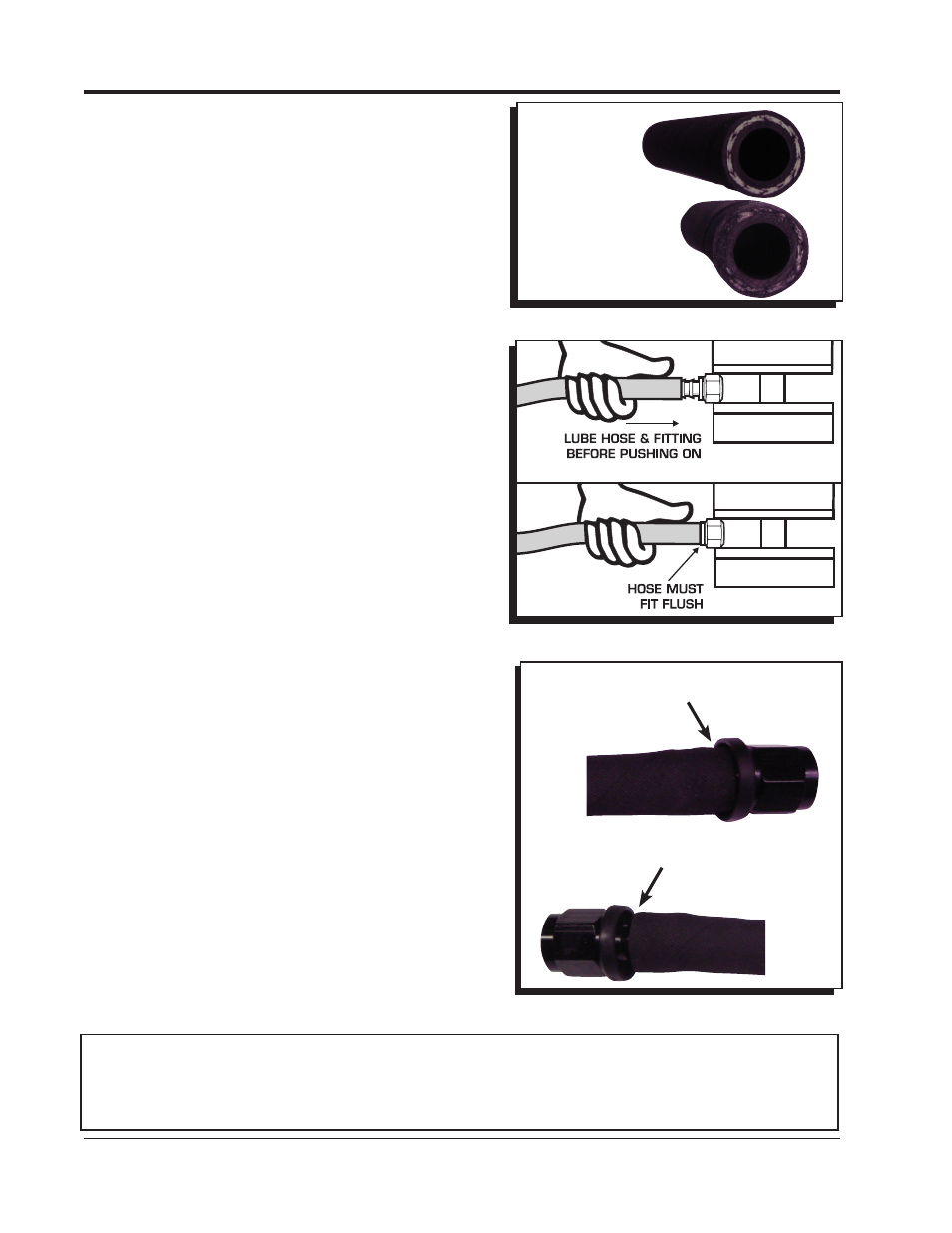
Figure 6 Installing Fuel Hose to the Push-Lock Fittings.
Figure 7 Installed Push-Lock Fitting.
END OF HOSE IS FLUSH
WITH THE THIN EDGE
OF THE BEAUTY RING.
Properly Installed Push-Lock Fitting
Figure 5 Severing the Hose Properly.
CORRECT CLEAN,
SQUARE CUT
INCORRECT
JAGGED, ROUGH
CUT RESULTS IN
A COMPROMISED
CONNECTION
E X C E S S I V E G A P T O
BEAUTY RING RESULTS
IN A COMPROMISED
CONNECTION.
Improperly Installed Push-Lock Fitting