MSD 2910 Atomic EFI Master Kit Installation User Manual
Page 17
INSTALLATION INSTRUCTIONS
17
M S D
• W W W . A T O M I C E F I . C O M • ( 9 1 5 ) 8 5 5 - 7 1 2 3 • F A X ( 9 1 5 ) 8 5 7 - 3 3 4 4
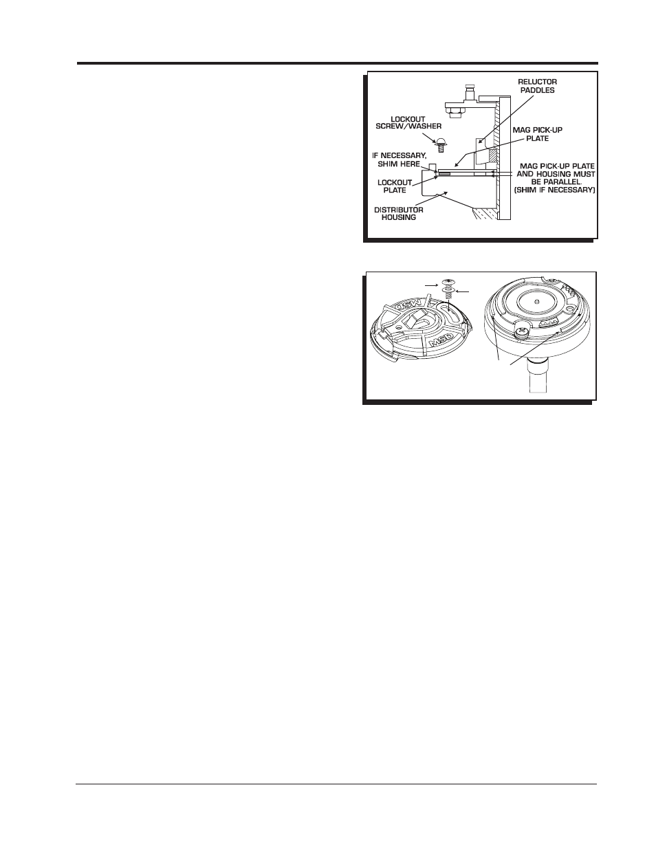
b. Remove the snap ring that holds the magnetic
pickup assembly in place.
c. Gently lift up on the mag pickup plate and slide
the vacuum canister out.
d. Install the Lockout Plate in place of the canister.
Install the two retaining screws.
e. Install the supplied screw and washer through
the Lockout and tighten.
f. It is important to make sure the pickup plate
is parallel with the housing of the distributor
(Figure 16). If it is cocked or slanted, the
paddles of the reluctor may contact the pickup.
g. Check the clearance by rotating the distributor
shaft. If necessary, use the supplied shims
under the Lockout hold-down to correctly
position the pickup plate.
Note: If no shims were required, use one beneath
the washer of the Lock-Out Hold Down Screw.
INSTALL THE ADJUSTABLE ROTOR
1. Install the new adjustable rotor (MSD PN 84211 or
PN 8421).
2. Set the phasing of the adjustable rotor based on the information below.
ROTOR PHASING
To phase your rotor properly for the Atomic EFI to control ignition timing, set it retarded (opposite
rotation) at 15˚ on the rotor indicator. Remove and lockout the vacuum advance, if applicable, on all
distributors except Fords*.
* Distributor PN 8573 will need the vacuum canister removed and locked out.
Distributors PN 8386 and 8387 keep the vacuum canister in place.
Please see Appendix A for a complete list of our distributors, the required adjustable rotor, and other
applicable notes.
INSTALL THE DISTRIBUTOR
1. Position the engine at 15° Before Top Dead Center (BTDC).
2. Install the distributor making sure the rotor comes to rest pointing at the number one terminal of
the distributor cap.
3. Tighten the distributor clamp – but leave it so the distributor can be moved.
4. Connect the distributor’s magnetic pickup to the matching connector on the throttle body.
5. Connect the Yellow wire of the Atomic to the White input wire on the MSD Ignition Control. This is
the trigger signal for the ignition.
6. Install the cap and spark plug wires.
Idle RPM - Set this to the rpm at which you would like the Atomic to start advancing ignition timing
off idle.
Total RPM - This is the rpm at which the Atomic should have full ignition timing.
Figure 17 Checking Installation of the Lockout Plate.
DOME MUST
FACE UP
5/16” SCREW
CLOCKING
TABS
POSITION ON
BASE AND
ROTATE INTO
POSITION
Figure 18 Two Piece Rotor, PN 84211.