MSD 2910 Atomic EFI Master Kit Installation User Manual
Page 5
INSTALLATION INSTRUCTIONS
5
M S D
• W W W . A T O M I C E F I . C O M • ( 9 1 5 ) 8 5 5 - 7 1 2 3 • F A X ( 9 1 5 ) 8 5 7 - 3 3 4 4
The WBO2 can be installed downstream of either exhaust bank. The sensor connects to the Power Module,
so install the sensor on the bank closest to where you plan to mount the Module. The bung should be
installed by a qualified exhaust technician and pressure tested. Proper installation of the oxygen sensor is
critical to the performance of the Atomic EFI. Improper installation could lead to engine damage.
1. Locate the ideal spot to install the WBO2.
a. This location should be 2-4 inches after the exhaust collector. The sensor must be more than
18 inches forward of the exhaust tip. For applications where short or open headers are used,
install the WBO2 in the primary tube of the rear cylinder at least 8 inches away from the exhaust
port. The Atomic will not work on “Zoomie” style headers.
b. The WBO2 sensor should be at least 10˚ above horizontal to allow condensation runoff. Without
this angle the sensor is significantly more likely to sustain water damage (Figure 2).
c. Never place a WBO2 on the outside of a bend.
d. The WBO2
must be mounted in the exhaust prior to any catalytic converter, if applicable.
2. Drill a 7/8” hole in the exhaust where the WBO2 will go.
3. Weld in the supplied bung. Ensure the weld goes completely around the bung and is air tight.
4. Insert supplied plug in bung. Never run the vehicle with a WBO2 installed but not powered; it will
damage the sensor.
5. When completing the Atomic EFI installation, remove the plug and insert the WBO2 for use. MSD
suggests using a small amount of anti-seize on the threads.
Note: The Atomic EFI is extremely sensitive to air leaks in the exhaust system. Any air leak between
the engine and the WBO2 will cause the Atomic to have false readings, which can lead to poor
engine performance, misfires, and an inability to properly auto-tune. Extended running of the
Atomic EFI with an exhaust leak can result in detonation and severe engine damage. Improper
installation of the oxygen sensor, and any damage that may result from such an installation, is
not covered by the manufacturer’s warranty.
THROTTLE BODY
Parts Required, not included:
4 – Retaining Stud Kit for the throttle body
Throttle linkage connection/brackets
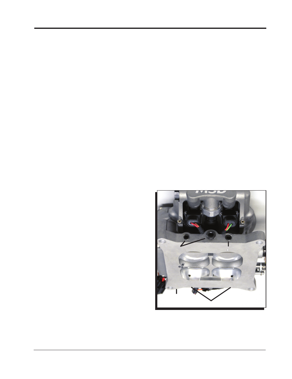
Figure 3 Vacuum Ports.
MANIFOLD
PORTED
MANIFOLD
The Atomic Throttle Body will bolt in place on
intake manifolds designed for a square bore style
carburetor. It is designed to accept common throttle
linkage adapters and brackets. A throttle ball stud
is supplied but no other linkage components are
included. Accessory kits are available through many
accessory or carburetor companies.
There are two fuel inlets, a forward and rear fuel
inlet. Only one needs to be connected on a PWM
(returnless) style system as fuel is delivered to either
side through an internal fuel rail. The passenger
side of throttle body, where the MSD is machined,
is the Electronic Control Unit (ECU). This is the
brains of the Atomic fuel system and where all of
the fuel calculations are made to give your vehicle
exceptional performance.
VACUUM PORTS
Before installing the throttle body, note the engine’s need for vacuum accessories. The Atomic has five
vacuum ports, ported and manifold, to cover accessories such as a power brake booster (Figure 3). Four
ports are 1/8" NPT and one is 1/4" NPT.
BOOST
REFERENCE
PORT