Power module installation, Power module wiring (figure 21) – MSD 2957 Atomic LS Master Early Truck Kit (GEN III 1999-2007) Installation User Manual
Page 9
INSTALLATION INSTRUCTIONS
9
M S D
• W W W . A T O M I C E F I . C O M • ( 9 1 5 ) 8 5 5 - 7 1 2 3 • F A X ( 9 1 5 ) 8 5 7 - 3 3 4 4
POWER MODULE INSTALLATION
The Power Module of the Atomic EFI system handles high
current circuits such as the fuel pump and WBO2. The unit has
two ports for the MSD CAN system as well as a wiring harness.
The CAN ports will provide communication between the Power
Module, the passenger side fuel/ECU rail and the Handheld
Monitor. It is important to select a proper mounting location
for the Power Module. The unit can be mounted in the interior
or the engine compartment as long as it is away from direct
heat sources. It is not recommended to mount the unit in an
enclosed area, such as the glove box. When a suitable location
is found, make sure all wires reach their connections. Also
be sure that the CAN port can be accessed for use with the
Handheld Monitor. Use the
Power Module as a template
and mark the location of the
holes. Use a size #20 drill
bit to prepare a hole for the
supplied self tapping screws.
Assemble the sleeves in the
power module (Figure 20).
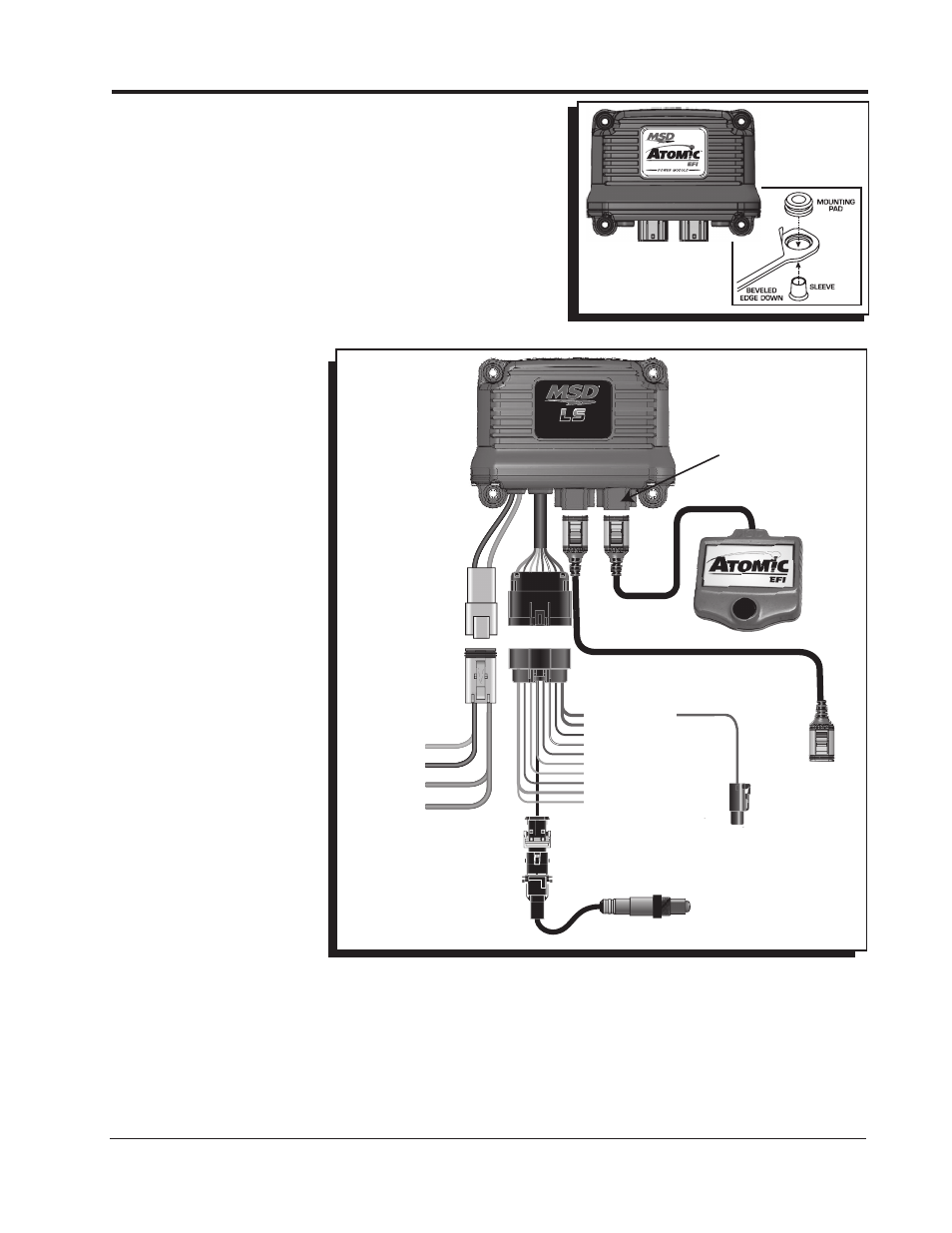
POWER MODULE
WIRING (Figure 21)
Not all of the wires from
the Power Module need to
be connected for proper
operation of the Atomic LS
Truck kit. Some of the wires
such as the nitrous input or
electric fan controls, only
need to be connected if their
functions are being used.
In the chart labeled Power
Module Wiring, wires marked
“REQ” must be connected
for the system to operate
while those marked “OPT”
are optional depending on
the features needed. For the
initial installation and start
up, it is recommended to
connect only the required
wires.
NOTE: The Power Module
uses two heavy gauge (Red)
wires that connect to the
battery. Both leads must be
connected in order for the
Power Module and Atomic LS Truck kit to operate correctly.
• Connect the CAN from the fuel rails into the center CAN port on the Power Module.
• Connect the Handheld Monitor to the CAN port on the Can Port on the right side of the Power Module.
• Connect the 16-pin GT connector harness included in the kit.
• Connect the 4-pin Deutsch connect harness included in the kit.
• Connect the wideband O2 sensor included in the kit.
• Make all the necessary electrical connections.
Figure 20 Mounting Hardware.
®
LS
FUEL PUMP
GROUND
BATTERY 1*
BATTERY 2*
CAN
ONLY
HANDHELD
MONITOR
RED SLED POWER
RED FAN 1
DARK BLUE LAUNCH
BROWN/WHITE NITROUS
BROWN SPEED REF (-)
LT BLUE SPEED (+)
GRAY TACH
RED SW 12V
ORANGE FAN 2
LT GREEN MIL GROUND
IP
VM
H-
H+
IA
UN
RED
YELLOW
BLK/WHT
BLK/RED
GREEN
BLACK
TO PASSENGER
FUEL RAIL
CAN TO
PASSENGER
FUEL RAIL
CONTROLLER
MONITOR
CONNECTOR
ONLY
* BATTERY 1 AND 2
MUST BOTH BE
CONNECTED
ORANGE
BLACK
HEAVY RED
HEAVY RED
Figure 21 Power Module Wiring Diagram.