MSD 2957 Atomic LS Master Early Truck Kit (GEN III 1999-2007) Installation User Manual
Page 12
12
INSTALLATION INSTRUCTIONS
M S D
• W W W . M S D P E R F O R M A N C E . C O M • ( 9 1 5 ) 8 5 5 - 7 1 2 3 • F A X ( 9 1 5 ) 8 5 7 - 3 3 4 4
WARNING: MSD’s Push-Lock fittings are designed
for use with the MSD fuel hose only. Do
not use the MSD fuel hose with other
fittings. Do not use MSD Push-Lock
fittings with other fuel hose. Compatibility
issues may cause fuel leaks. Fuel Inlet
Fittings and Cross-Over Line: LS engines
require a cross-over fuel line to route the
fuel from one bank to the other. This is
typically done at the front of the engine.
Due to the variety of intake manifolds
and accessories a cross-over line must
be made for each application.
The supplied MSD Push-Lock AN
fittings are designed only for use with
the supplied fuel hose (Aeroquip AQP
FC598). We do not recommend mixing
Push-Lock style fittings and hoses from
different manufacturers. Doing so may
result in fuel leaks and expose other
dangerous incompatibilities.
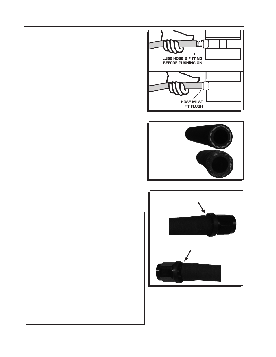
Figure 24 Installing Fuel Hose to the Push-Lock Fittings.
Figure 25 Severing the Hose Properly.
CORRECT CLEAN,
SQUARE CUT
Figure 26 Installed Push-Lock Fitting.
END OF HOSE IS FLUSH
WITH THE THIN EDGE
OF THE BEAUTY RING.
Properly Installed Push-Lock Fitting
INCORRECT
JAGGED, ROUGH
CUT RESULTS IN
A COMPROMISED
CONNECTION
E X C E S S I V E G A P T O
BEAUTY RING RESULTS
IN A COMPROMISED
CONNECTION.
Improperly Installed Push-Lock Fitting
MSD supplies a length of fuel hose and two 90° -6AN
fittings to prepare a fuel crossover line. The fittings utilize
Push-Lock technology and are designed exclusively for
use with the supplied hose. These fittings do not use
clamps, however it is imperative to follow the installation
instructions.
Proper installation begins with a clean, square cut of
the hose. A hose cutting tool or new razor blade are
recommended. When installing the hose it is important
that the hose is pushed on all the way to the thin beauty
ring (Figure 24). This means the hose should fully overlap
the inboard barb. Too little of engagement, as well as over-
engagement, will result in a compromised connection
that is prone to failure.
1. Determine the length of hose needed. Mark the hose
and cut it using a hose cutter or new razor blade.
There should be minimal disturbance of the outer
jacket, braids and inner liner. The cut plane should
be perpendicular to the hose axis. (Figure 25).
2. Before installing the hose to the fitting, it is important
to anchor the fitting. Proper installation cannot be
achieved by holding the hose and fitting in your hands.
For best results, the hose should be installed with
minimal twisting or pausing.
3. Apply a light coat of oil to the barbs on the fitting and
inside the hose. Use care not to get oil on the outside
of the hose as it will be impossible to get a firm grip
on the hose.
4. With the fitting anchored securely, push the hose over
the barbs. The hose is properly installed when it is flush
with the thin edge of the beauty ring (Figure 26). At
this point, the hose end should have rolled over the
inboard barb.