Fuel rail/ecu wiring, Fuel rail cover installation overview – MSD 2957 Atomic LS Master Early Truck Kit (GEN III 1999-2007) Installation User Manual
Page 6
6
INSTALLATION INSTRUCTIONS
M S D
• W W W . M S D P E R F O R M A N C E . C O M • ( 9 1 5 ) 8 5 5 - 7 1 2 3 • F A X ( 9 1 5 ) 8 5 7 - 3 3 4 4
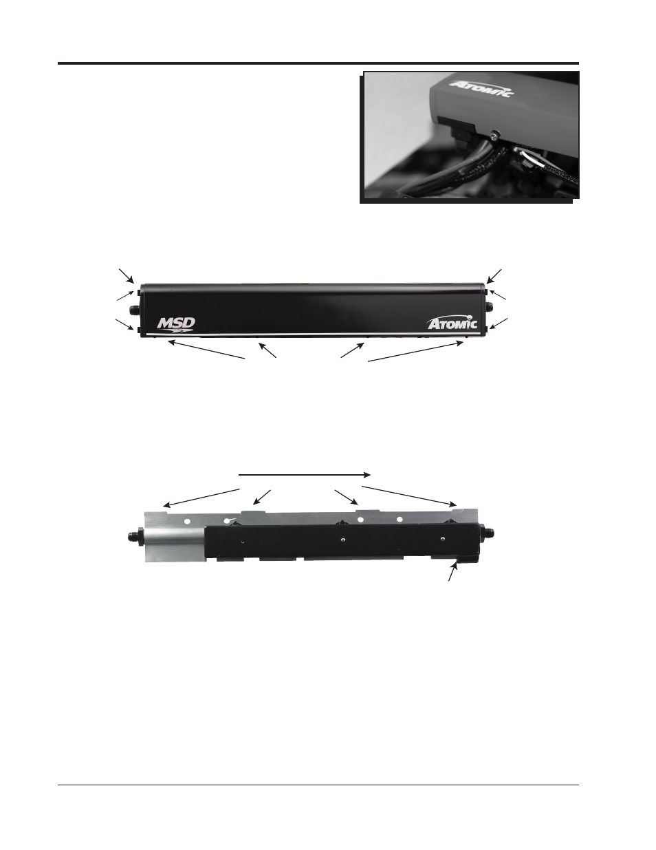
19. Secure the rail covers onto the fuel rail with the
supplied 8/32 socket head cap screws (Figure 15).
20. Install the fuel rail end cap onto the cover and secure
it with the supplied 6/32 socket head cap screws.
FUEL RAIL/ECU WIRING
The Atomic LS Truck kit has several adapter harnesses in order for the kit to install with all the different
variations of the truck motors. These adapter harnesses plug into the connectors found on the rails
themselves. The IAC and TPS connectors are on both rails to accommodate the different throttle
body configurations.
Air Conditioning kick up (AC): When 12v is applied to this wire, the ECU will kick up the IAC count and
Fan #1 to compensate for the engine load change created by the air conditioning compressor.
Alternator: The kit is supplied with a harness that has two alternator connectors on one end. This is
done to accommodate the two different alternator ends used by GM. Identify which connector
is needed, and cut the other connector off. Use the heatshrink caps provided in the parts bag
to seal the wire end.
Cam Sensor: The kit supports both the 1x and 4x cam sensors. The easiest way to identify the cam
sensor on a stock engine would be by locating the sensor on the motor. The 4x sensor is
mounted on the timing chain cover. The 1x sensor is located on the back of the motor.
Figure 15 Fuel Rail Cover.
Follow these steps to install both covers. To remove the covers reverse the steps.
COVER - TOP VIEW
END CAP
END CAP
8/32 SCREWS ON BACK OF COVER
6/32
SCREWS
6/32
SCREWS
SLIDE TOWARD REAR TO ENGAGE.
FRONT
REAR
LOCKING TABS
EDGE OF
BLACK MOLD
COVER - TOP VIEW
END CAP
END CAP
8/32 SCREWS ON BACK OF COVER
6/32
SCREWS
6/32
SCREWS
SLIDE TOWARD REAR TO ENGAGE.
FRONT
REAR
LOCKING TABS
EDGE OF
BLACK MOLD
FUEL RAIL COVER INSTALLATION
OVERVIEW
1. Line the end of the fuel rail cover up with the edge of the black mold on the rear of the fuel rail (Figure 14).
2. Slide the cover towards the rear of the engine to engage the locking tabs on the fuel rail.
3. Install the 8/32 screws that secure the covers to the fuel rails.
4. Install the end caps and secure with the 6/32 screws.