MSD 2957 Atomic LS Master Early Truck Kit (GEN III 1999-2007) Installation User Manual
Page 5
INSTALLATION INSTRUCTIONS
5
M S D
• W W W . A T O M I C E F I . C O M • ( 9 1 5 ) 8 5 5 - 7 1 2 3 • F A X ( 9 1 5 ) 8 5 7 - 3 3 4 4
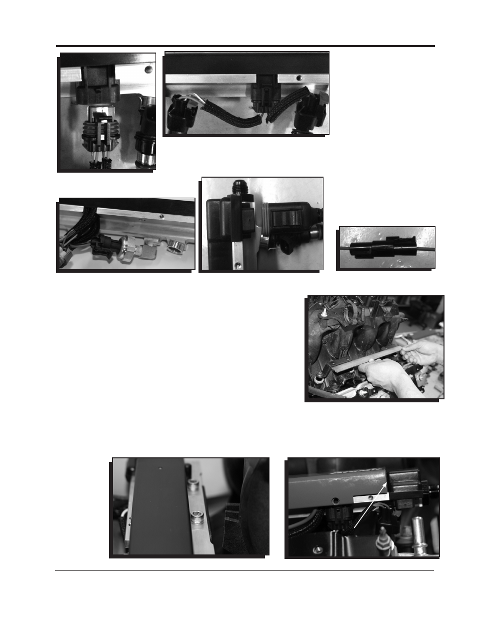
Figure 7 Injector Rail
Connection.
Figure 8 Injector Pigtail.
Figure 9 Fuel Pressure Sensor.
Figure 10 CAN Cable.
Figure 11 Rail Power.
12. Place the spacer/bushing/rail bracket assemblies onto the intake
manifold.
13. Use the torque sequence on page 4, Figure 4 to torque the
manifold bolts down correctly. Bolts #9 and #10 will use the stock
length bolts/bushings.
14. Check the rail brackets with a straight edge (Figure 12).
15. Install the rails onto the manifold. Use the supplied 6mm bolts to
secure the rails to the rail brackets. Torque to 85 in lb – 87 in. lb.
(Figure 13).
16.
STOP. Visually inspect and ensure all the injectors are sitting evenly
and the injector o-rings are not pinched or visible.
Failure to install
the injectors correctly can result in fuel leaks and engine fire.
17. Begin routing the sensor harnesses and plugging them into the
appropriate sensors.
18. Line the end of the fuel rail cover up with the edge of the black
mold on the rear of the fuel rail (Figure 14). Slide the cover towards
the rear of the engine to engage the locking tabs on the fuel rail.
(Figure 15).
Figure 12 Straight Edge Check of
Brackets.
Figure 13 Rail to Bracket Bolts.
Figure 14 Fuel Rail Cover.
END OF COVER /
EDGE OF BLACK
MOLD.