2 nav page group, 3 default nav page – Garmin GPS 400 User Manual
Page 28
GPS 400 Pilot’s Guide and Reference
190-00140-60 Rev. H
SECTION 2
NAV PAGES
2-2
2.2 NAV PAGE GROUP
The NAV Page Group includes seven pages (Figure
3-2). While viewing any NAV page, turn the small right
knob to select a different NAV page. The pilot may
find this selection process convenient to cycle between
the Default NAV Page and the Map Page, two of the
most frequently used pages. Other pages are provided
for terrain information, (if configured for TERRAIN) to
list frequencies for the flight plan, to show the current
position, to display current satellite reception, and to
make vertical navigation settings.
Default NAV
Map
TERRAIN
NAV/COM
Position
Satellite Status
VNAV
(if configured)
Figure 2-2 NAV Pages
NOTe: The NaV Page Group may have eight or
nine NaV pages available when the GPS 400
installation includes connection to traffic and/or
weather information sources. See Section 10 of
this manual for more information.
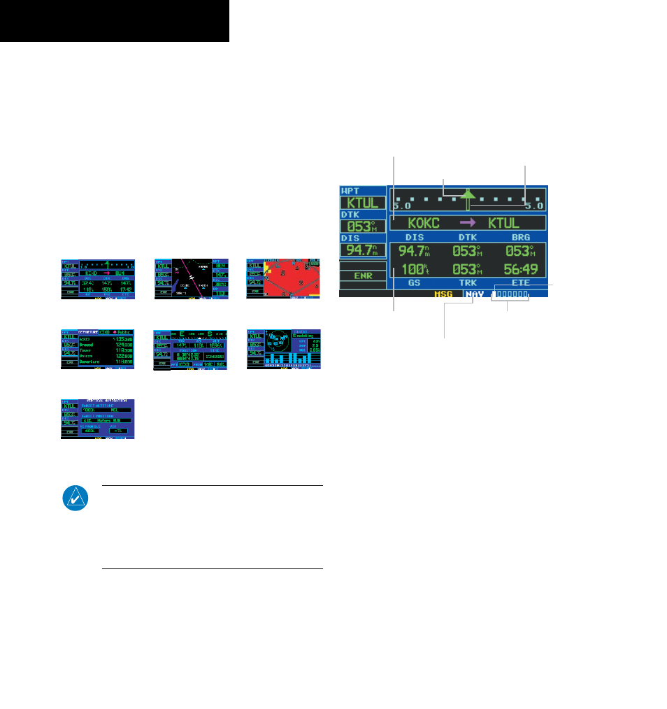
2.3 DEFAULT NAV PAGE
The first NAV page is the Default NAV Page (Figure
2-3). This page may be quickly selected from any page by
pressing and holding the CLR Key.
Figure 2-3 Default NAV Page
Course Deviation
Indicator (CDI)
User-selectable
Data Fields
Active Leg of Flight Plan
TO/FROM Flag
Number of Pages in
Current Page Group
Position of
Current Page
within Current
Page Group
Current Page Group
The Default NAV Page displays a graphic course
deviation indicator (CDI) across the top of the page.
Unlike the angular limits used on a mechanical CDI
coupled to a VOR or ILS receiver, full scale limits for this
CDI are defined by a GPS-derived distance (0.3, 1.0, or
5.0 nm), as indicated at both ends of the CDI. By default,
the CDI scale automatically adjusts to the desired limits
based upon the current phase of flight: enroute, terminal
area, or approach. The pilot may also manually select the
desired scale setting as outlined in Section 8.4.
The graphic CDI shows the aircraft’s position at the
center of the indicator, relative to the desired course (the
moving course deviation needle). As with a traditional
mechanical CDI, when off course simply steer toward the
needle. The TO/FROM arrow in the center of the scale
indicates whether the aircraft is heading TO (up arrow)
the waypoint or FROM the waypoint (down arrow).