Main unit - input terminals – JVC DLA-X95R User Manual
Page 16
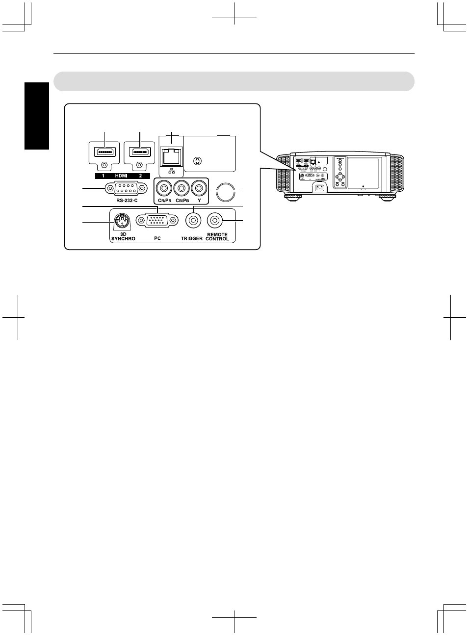
Main Unit - Input Terminals
.
A
B
C
D
F
E
G
I
H
Enlarged View of Rear Face
A
[HDMI 1] input terminal
B
[HDMI 2] input terminal
For connecting to devices that support HDMI output.
(p. 22)
It is fitted to the M3 lock hole. The depth of the screw
hole is 3 mm.
C
[LAN] terminal (RJ-45)
The projector can be controlled by connecting it to a
PC through the computer network for control
commands to be sent to the projector.
D
[RS-232C] terminal (D-sub 9-pin
male)
The projector can be controlled by connecting a PC to
this terminal.
* The LAN and RS-232C terminals cannot be used at the
same time. (p. 62)
E
[PC] Input terminal (D-sub 15-pin)
D
C
This is an input terminal used for PC signals (RGB
video signals and sync signals) only.
It can be connected to a PC monitor output terminal,
etc.
F
[3D SYNCHRO] terminal
By connecting a 3D SYNCHRO EMITTER (sold
separately) to this terminal, you can view 3D movies.
G
Component video input terminals
(RCA x 3)
For connecting to devices that support component
signal output.
It can be used as an input terminal for analog RGB (G
on Sync), component (Y, Cb, Cr), or DTV format (Y,
Pb, Pr) signals.
H
[TRIGGER] terminal (E)
Output terminal for DC 12V, 100 mA power supply. It
is used for sending output signals to control elevating
screens for which the use of a SCREEN TRIGGER is
supported.
Note that improper connection may damage the
projector. (Tip=DC +12 V, Sleeve=GND)
I
[REMOTE] terminal (stereo mini
jack)
Use this terminal when a remote control unit is not
usable, such as when the projector is installed in a
dedicated box or for rear projection.
Connect an external remote sensor unit to the
projector unit.
For details on the external infrared sensor and
connecting cable, please contact your dealer.
16
Getting Started