3 front panel leds – ZyXEL Communications ES-3124PWR User Manual
Page 40
Dimension ES-3124PWR Ethernet Switch
3-6
Hardware Connections
The backup power supply constantly monitors the status of the internal power supply. The backup power supply
automatically provides power to the switch in the event of a power failure. Once the switch receives power from the
backup power supply, it will not automatically switch back to using the internal power supply even when the power
is resumed.
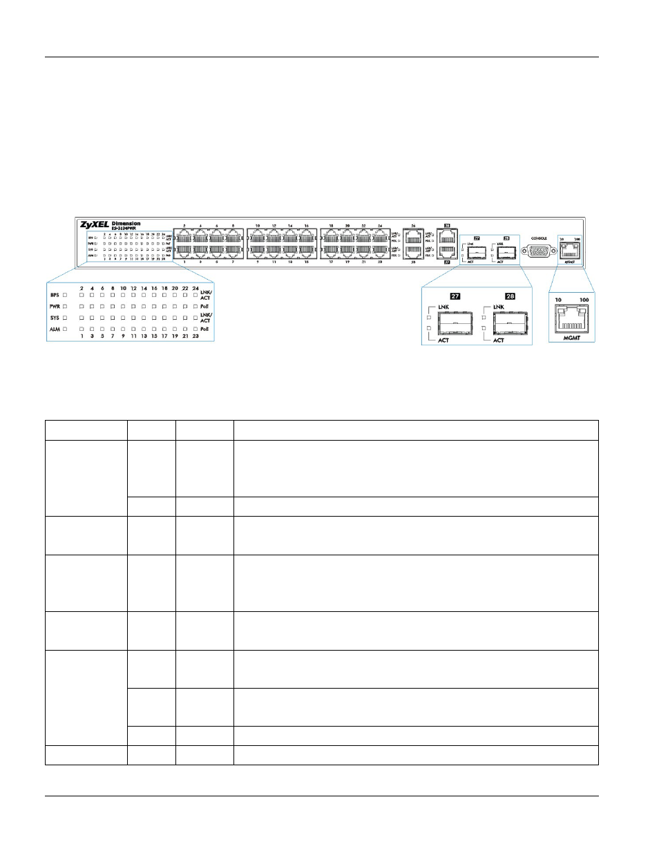
3.3 Front Panel LEDs
After you connect the power to the switch, view the LEDs to ensure proper functioning of the switch and as an aid
in troubleshooting. The front panel LEDs are as follows.
Figure 3-7 Front Panel LEDs
The following table describes the LED indicators on the front panel of an ES-3124PWR switch.
Table 3-2 ES-3124PWR: LED Descriptions
LED COLOR
STATUS
DESCRIPTION
Green Blinking
ON
OFF
The system is receiving power from the backup power supply.
The backup power supply is connected and active.
The backup power supply is not ready or not active.
BPS
Amber
Blinking The system cannot get power from the backup power supply.
PWR Green
ON
OFF
The system is turned on.
The system is off.
SYS Green
Blinking
ON
OFF
The system is rebooting and performing self-diagnostic tests.
The system is on and functioning properly.
The power is off or the system is not ready/malfunctioning.
ALM Red
ON
OFF
There is a hardware failure.
The system is functioning normally.
LNK/ACT
Green Blinking
ON
The system is transmitting/receiving to/from a 10 Mbps Ethernet network.
The link to a 10 Mbps Ethernet network is up.
Amber
Blinking
ON
The system is transmitting/receiving to/from a 100 Mbps Ethernet network.
The link to a 100 Mbps Ethernet network is up.
OFF
The link to a 100/10 Mbps Ethernet network is down.
PoE
Amber
ON
The switch is supplying power to the connected device that supports PoE.