Xilinx SP601 Hardware UG518 User Manual
Page 37
SP601 Hardware User Guide
37
UG518 (v1.1) August 19, 2009
Detailed Description
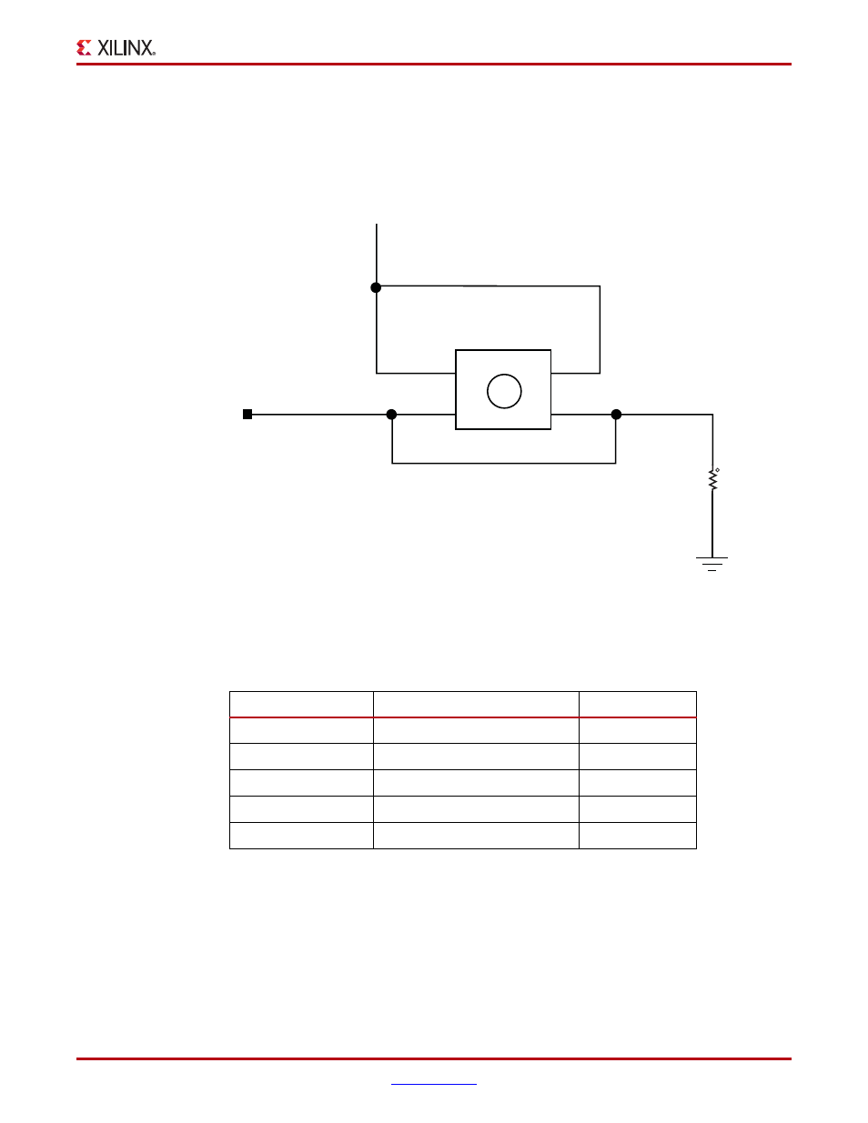
User Pushbutton Switches
The SP601 provides five active high pushbutton switches: SW6, SW4, SW5, SW7 and SW9.
The five pushbuttons all have the same topology as the sample shown in
Figure 1-25
. Four
pushbuttons are assigned as GPIO, and the fifth is assigned as a CPU_RESET.
Figure 1-25
and
Table 1-19
describe the pushbutton switches.
X-Ref Target - Figure 1-25
Figure 1-25:
User Pushbutton Switch (Typical)
Table 1-19:
Pushbutton Switch Connections
FPGA U1 Pin
Schematic Netname
Switch Pin
P4
GPIO_BUTTON_0
SW6.2
F6
GPIO_BUTTON_1
SW4.2
E4
GPIO_BUTTON_2
SW5.2
F5
GPIO_BUTTON_3
SW7.2
N4
CPU_RESET
SW9.2
VCC1V8
CPU_RESET
Pushbutton
1
1
2
4
2
SW9
R188
4.7K
5%
1/16W
3
P1
P2
P3
P4
UG518_25_070809