User dip switch – Xilinx SP601 Hardware UG518 User Manual
Page 36
36
SP601 Hardware User Guide
UG518 (v1.1) August 19, 2009
Chapter 1: SP601 Evaluation Board
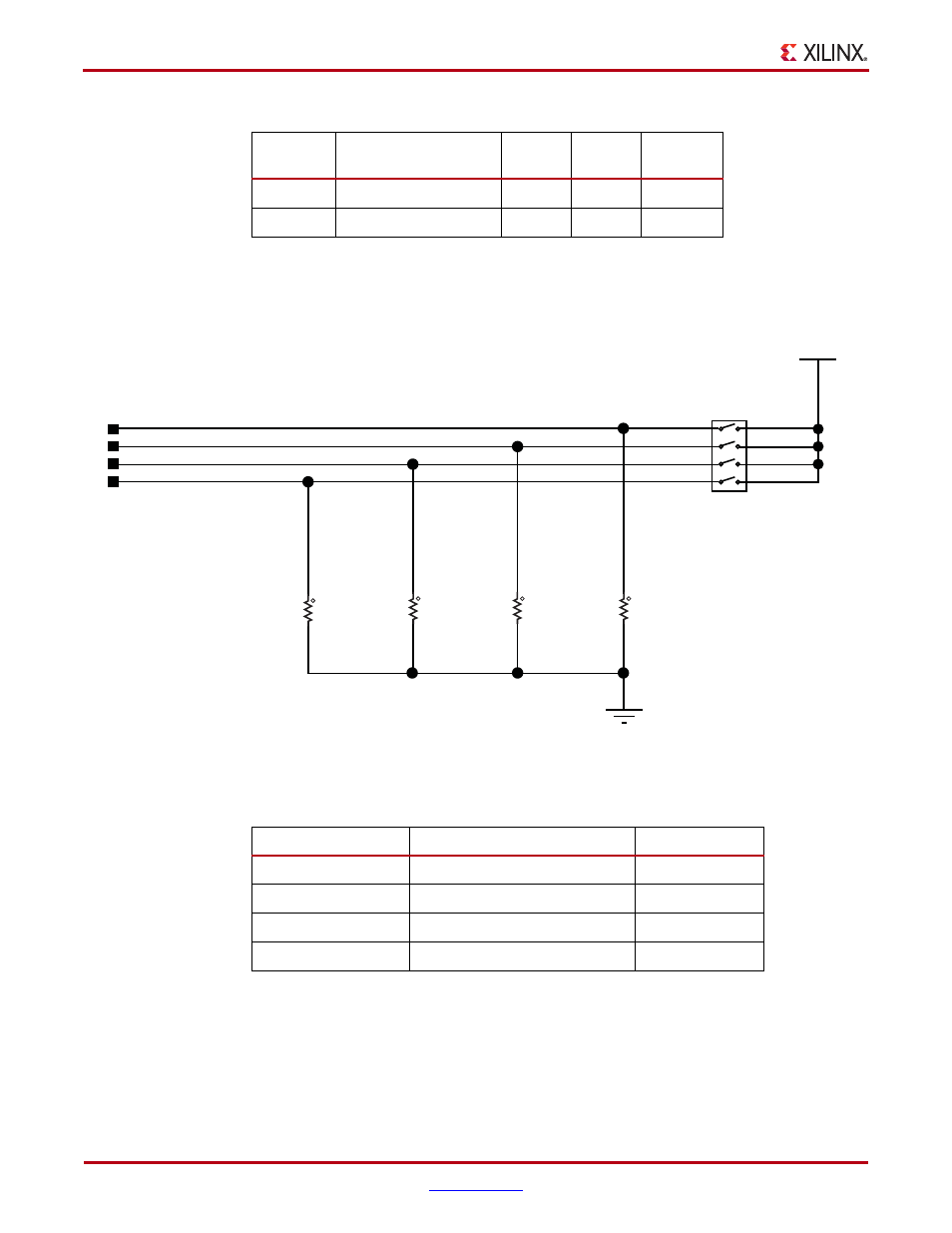
User DIP switch
The SP601 includes an active high four pole DIP switch, as described in
Figure 1-24
and
Table 1-18
.
DS13
GPIO_LED_2
Green
C4
DS14
GPIO_LED_3
Green
A4
Table 1-17:
User LEDs (Cont’d)
Reference
Designator
Signal Name
Color
Label
FPGA Pin
X-Ref Target - Figure 1-24
Figure 1-24:
User DIP Switch
UG518_24_070809
R22
4.7K
5%
1/16W
R21
4.7K
5%
1/16W
R20
4.7K
5%
1/16W
R19
4.7K
5%
1/16W
1
2
1
2
1
2
1
2
GPIO_SWITCH_0
GPIO_SWITCH_1
GPIO_SWITCH_2
GPIO_SWITCH_3
VCC2V5
1
8
2
7
3
6
4
5
SW8
SDMX-4-X
Table 1-18:
User DIP Switch Connections
FPGA U1 Pin
Schematic Netname
SW8 Pin Number
D14
GPIO_SWITCH_0
1
E12
GPIO_SWITCH_1
2
F12
GPIO_SWITCH_2
3
V13
GPIO_SWITCH_3
4