Usb-to-uart bridge – Xilinx SP601 Hardware UG518 User Manual
Page 25
SP601 Hardware User Guide
25
UG518 (v1.1) August 19, 2009
Detailed Description
References
See the Marvell Alaska Gigabit Ethernet Transceiver product page for more information at
.
Also, see the Xilinx Tri-Mode Ethernet MAC User Guide at
6. USB-to-UART Bridge
The SP601 contains a Silicon Labs CP2103GM USB-to-UART bridge device (U4) which
allows connection to a host computer with a USB cable. The USB cable is supplied in this
evaluation kit (Type A end to host computer, Type Mini-B end to SP601 connector J9).
Table 1-10
details the SP601 J9 pinout.
Xilinx UART IP is expected to be implemented in the FPGA fabric. The FPGA supports the
USB-to-UART bridge using four signal pins, transmit (TX), receive (RX), Request to Send
(RTS), and Clear to Send (CTS).
Silicon Labs provides royalty-free Virtual COM Port (VCP) drivers which permit the
CP2103GM USB-to-UART bridge to appear as a COM port to host computer
communications application software (for example, HyperTerm or TeraTerm). The VCP
device driver must be installed on the host PC prior to establishing communications with
the SP601. Refer to the SP601 Getting Started Guide for driver installation instructions.
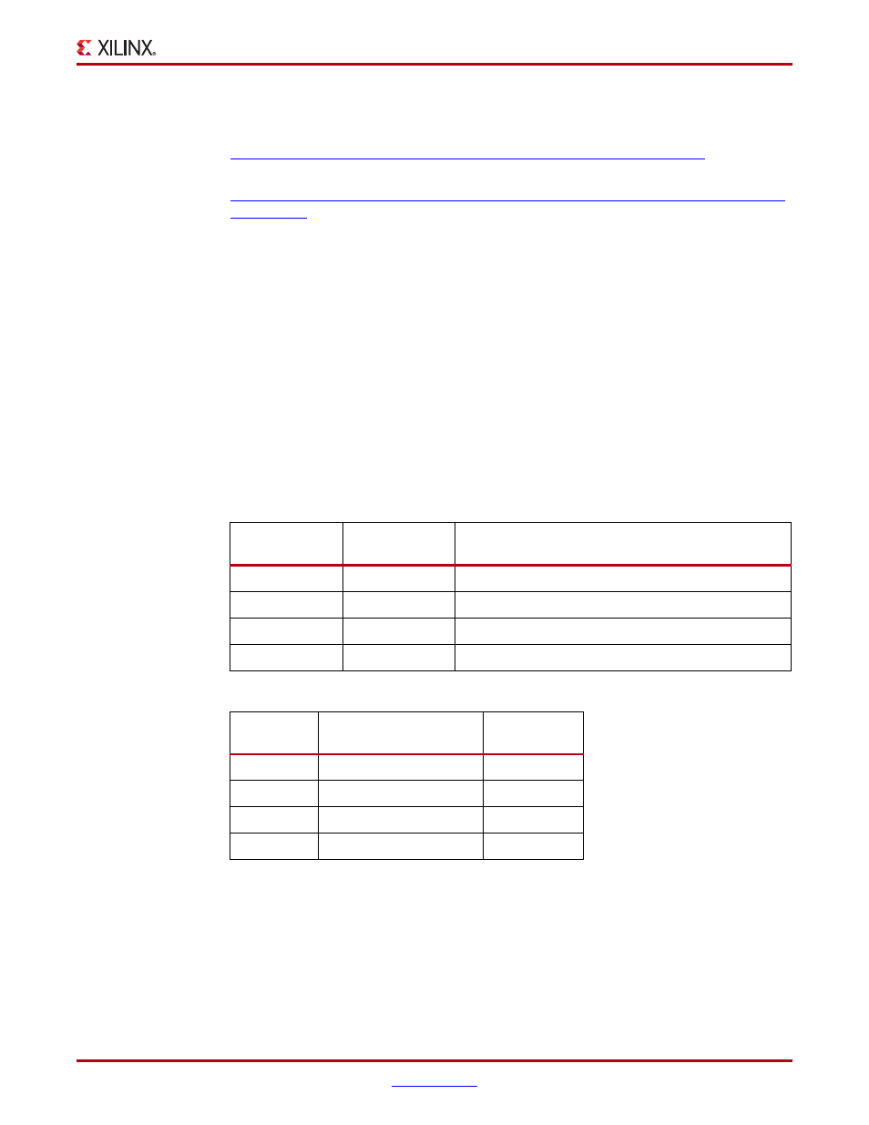
Table 1-10:
USB Type B Pin Assignments and Signal Definitions
USB Connector
Pin
Signal Name
Description
1
VBUS
+5V from host system (not used)
2
USB_DATA_N
Bidirectional differential serial data (N-side)
3
USB_DATA_P
Bidirectional differential serial data (P-side)
4
GROUND
Signal ground
Table 1-11:
CP2103GM Connections
FPGA U1
Pin
Schematic Netname
U4 CP2103GM
U10
USB_1_CTS
22
T5
USB_1_RTS
23
L12
USB_1_RX
24
K14
USB_1_TX
25
X-Ref Target - Figure 1-12
NET "USB_1_CTS" LOC = "U10";
NET "USB_1_RTS" LOC = "T5";
NET "USB_1_RX" LOC = "L12";
NET "USB_1_TX" LOC = "K14";
Figure 1-12:
UCF Location Constraints for CP2103GM Connections