1 example 1, 2 example 2, 1 example 1 7.4.1.2 example 2 – ZyXEL Communications Internet Security Appliance ZyWALL5UTM 4.0 User Manual
Page 128: Figure 47 least load first example
ZyWALL 5/35/70 Series User’s Guide
Chapter 7 WAN Screens
128
7.4.1.1 Example 1
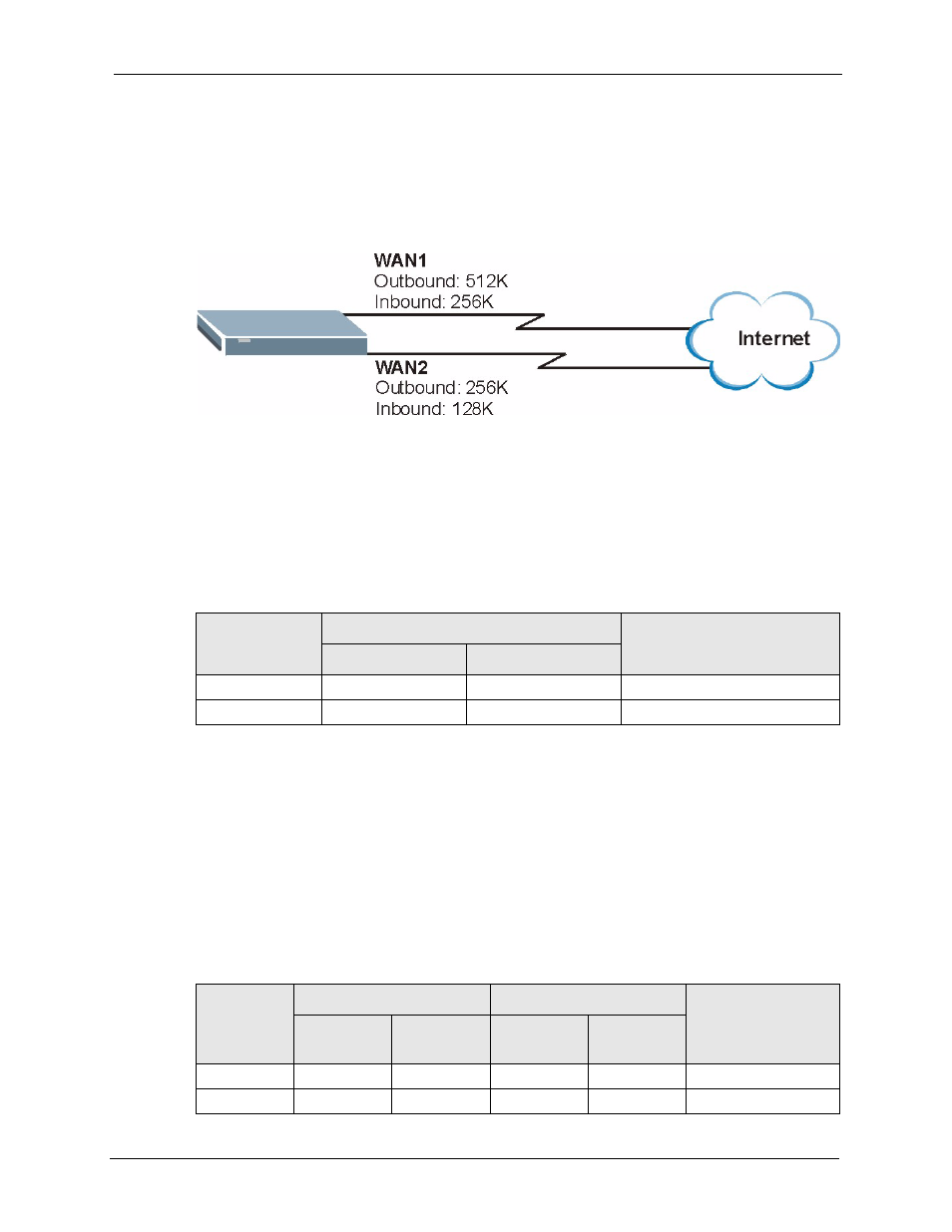
The following figure depicts an example where both the WAN ports on the ZyWALL are
connected to the Internet. The configured available outbound bandwidths for WAN 1 and
WAN 2 are 512K and 256K respectively.
Figure 47 Least Load First Example
If the outbound bandwidth utilization is used as the load balancing index and the measured
outbound throughput of WAN 1 is 412K and WAN 2 is 198K, the ZyWALL calculates the
load balancing index as shown in the table below.
Since WAN 2 has a smaller load balancing index (meaning that it is less utilized than WAN 1),
the ZyWALL will send the subsequent new session traffic through WAN 2.
Table 30 Least Load First: Example 1
INTERFACE
OUTBOUND
LOAD BALANCING INDEX
(M/A)
AVAILABLE (A)
MEASURED (M)
WAN 1
512 K
412 K
0.8
WAN 2
256 K
198 K
0.77
7.4.1.2 Example 2
This example uses the same network scenario as in
, but uses both the
outbound and inbound bandwidth utilization in calculating the load balancing index. If the
measured inbound stream throughput for both WAN 1 and WAN 2 is 102K, the ZyWALL
calculates the average load balancing indices as shown in the table below.
Since WAN 1 has a smaller load balancing index (meaning that it is less utilized than WAN 2),
the ZyWALL will send the next new session traffic through WAN 1.
Table 31 Least Load First: Example 2
INTERFACE
OUTBOUND
INBOUND
AVERAGE LOAD
BALANCING INDEX
(OM / OA + IM / IA) / 2
AVAILABLE
(OA)
MEASURED
(OM)
AVAILABLE
(IA)
MEASURED
(IM)
WAN 1
512 K
412 K
256 K
102 K
( 0.8 + 0.4) / 2 = 0.6
WAN 2
256 K
198 K
128 K
102 K
( 0.77 + 0.8 ) / 2 = 0.79