Direct exhaust — sidewall, Gv90, Boiler manual – Weil-McLain GV90+ User Manual
Page 51
Part number 550-142-054/0411
51
GV90+
gas
-
fired
water
boiler
— Boiler Manual
DIRECT EXHAUST — Sidewall
DO NOT sidewall vent DIRECT EX-
HAUST APPLICATIONS
at altitudes
above 5,500 feet. Sidewall venting is
only allowed for
DIRECT VENT
ap-
plications (ducted combustion air)
at altitudes above 5,500 feet.
Allowable vent/air pipe materials &
lengths
Use only the vent materials and kits
listed in Figure 40, page 33. Provide
pipe adapters if specified.
1. Locate the termination such that the total air
piping and vent piping from the boiler to the
termination will not exceed the maximum
length given in Figure 39, page 32.
Determine termination location
1. The air and vent terminations must be
installed as shown in Figure 61 and in Fig-
ure 62, page 52.
2. The terminations must comply with clearances
and limitations shown in Figure 41, page 35.
3. Locate the termination so it is not likely to be
damaged by foreign objects, such as stones
or balls, or subject to buildup of leaves or
sediment.
Multiple vent/air terminations
1. Terminate each vent of multiple direct exhaust
GV90+ boilers as described in this manual for
individual vents.
2. Space terminations as required for best instal-
lation practices and required maintenance.
a. External venting greater than 4 feet
requires an enclosure around the vent
pipe. The vent termination must exit
through the enclosure as shown in Fig-
ure 61, page 51, maintaining all required
clearances.
Prepare wall penetration
Where the vent penetrates an outside
wall, the annular space around the
penetration must be permanently
sealed using approved materials to
prevent entry of combustion prod-
ucts into the building.
1. Wall penetration:
a. Cut a rough opening large enough to clear
the diameter of the metal thimble used.
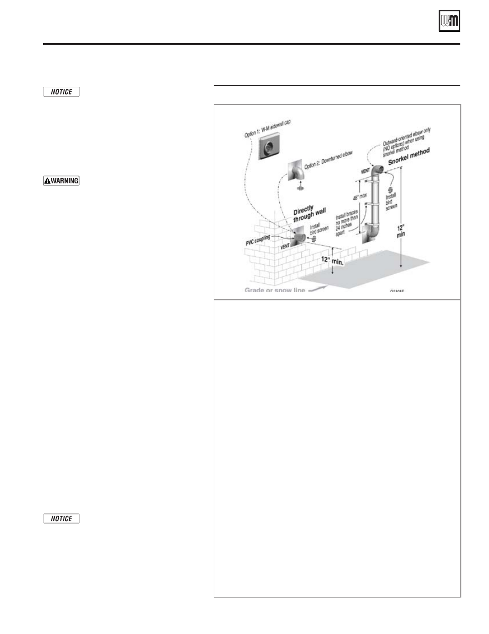
Figure 61
INSTALLATION SEQUENCE — Direct exhaust sidewall
Step 1 Read and follow all instructions in this manual. DO NOT proceed with
vent installation until you have read page 29 through page 35,
page 49 and page 50.
Step 2 Install the boiler in a location that allows proper routing of vent piping to
the selected sidewall location.
Step 3 Make sure the selected sidewall termination location complies with Fig-
ure 41, page 35.
Step 4 Use only the vent materials listed in Figure 40, page 33. Provide pipe adapt-
ers where required. Vent piping length must not exceed the value shown in
Figure 39, page 32.
Step 5 Prepare the sidewall penetration and secure the sidewall plate as instructed
in this section. See “Prepare wall penetration” on page 51 and “Termination
and fittings” on page 52.
Step 6 The vent piping can terminate using the Weil-McLain vent/air plate (without
air piping connected). It can also terminate using a coupling or down-turned
elbow, or snorkeled and terminated with an elbow. See illustration above.
The coupling or elbow must butt against the outside plate.
Step 7 Install vent piping between the boiler and the sidewall opening. Slope
horizontal piping downward toward the boiler at least 1/4 inch per foot.
See page 48 for general guidelines.
Step 8 Install pipe supports every 5 feet on both the horizontal and vertical runs.
Install a hanger support within 6 inches of any upturn in the piping.
Step 9 Attach the vent termination exterior piping, if used: Use any of the con-
figurations shown above, as needed to ensure clearance above grade or
snow line.
Step 10 The vent pipe may run up as high as 4 feet with no enclosure. The vent
pipe must be secured with braces, and all clearances and lengths must be
maintained. Space braces no further than 24 inches apart.
Step 11 External venting greater than 4 feet requires an insulated enclosure around
the vent and air pipes. The vent and air terminations must exit through
the enclosure as shown in the illustration above, maintaining all required
clearances.