Install water piping, Gv90, Boiler manual – Weil-McLain GV90+ User Manual
Page 14
Part number 550-142-054/0411
GV90+
gas
-
fired
water
boiler
— Boiler Manual
14
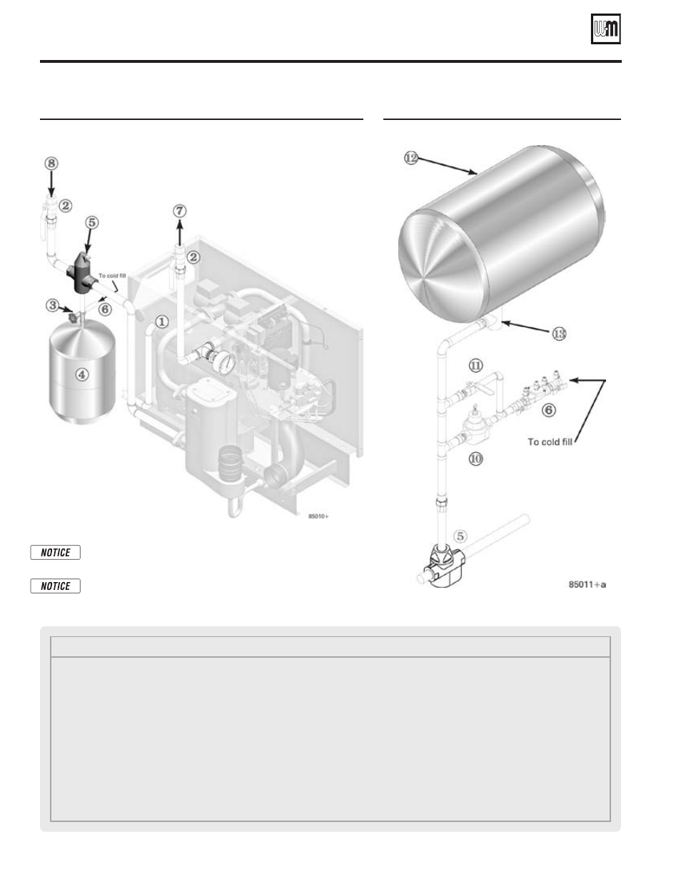
Figure 14
Piping to single-zone system using diaphragm- or
bladder-type expansion tank. Boiler connections are
1” NPT (supply from 1” tee, return to 1” recuperator
flange).
Figure 15
Piping closed-type expansion tank
Pipe diaphragm- or bladder-type expansion tanks to the bot-
tom of the separator.
Pipe closed-type (air in contact with water) tanks to the top of
the air separator. Always connect the fill line to the expansion
tank location, as shown above and in the suggested piping.
Install water piping
(continued)
Legend
1
Relief valve discharge piping — see page 12
2
Isolation valves
3
Fill valve
4
Diaphragm-type expansion tank — always locate as
shown in the suggested piping drawings in this manual
5
Air separator
• provide with automatic air vent ONLY when used
with diaphragm-type expansion tanks
• pipe air outlet to expansion tank when used with
close-type tanks
6
Cold fill line, with backflow preventer or check valve
when required by codes (see Figure 15 for typical com-
ponents)
7
System supply piping
8
System return piping
10
Pressure reducing valve, when used
11
Quick-fill bypass valve, when used
12
Closed-type expansion tank — always locate as shown
in the suggested piping drawings in this manual
13
Tank fitting