Ront, Anel, Ontrols – Vertex Standard FT-1000MP User Manual
Page 30: Page 28 o, Nb button, Tuner ] button, Vrf indicator, Vrf/mem ch knob, Vrf/mem ch knob sequence, Perating
Page 28
O
PERATING
M
ANUAL
NB Button
Pressing this button activates the IF Noise Blanker,
which may help reduce many different types of man-
made impulse noise (but not atmospherics). When the
Noise Blanker is activated, the LED inside button will
glow red.
You can select the Noise Blanker Type (for short-
duration pulses or for long-duration pulses) and its
blanking level via menu selection 2-8.
[TUNER] Button
This is the on/off switch for the MARK-V FT-1000MP
Field’s Automatic Antenna Tuner.
Pressing this button momentarily places the an-
tenna tuner in line between the transmitter final ampli-
fier and the main antenna jack. Reception is not af-
fected.
Pressing and holding this button for ½ second while
receiving in an amateur band activates the transmitter
for a few seconds while the automatic antenna tuner
rematches the antenna system impedance for mini-
mum SWR. The resulting settings are automatically
stored in one of the antenna tuner’s 39 memories, for
instant automatic recall later when the receiver is tuned
near the same frequency.
VRF Indicator
This indicator glows red when the VRF feature is
activated by pressing the [VRF] button on the Shuttle
Jog.
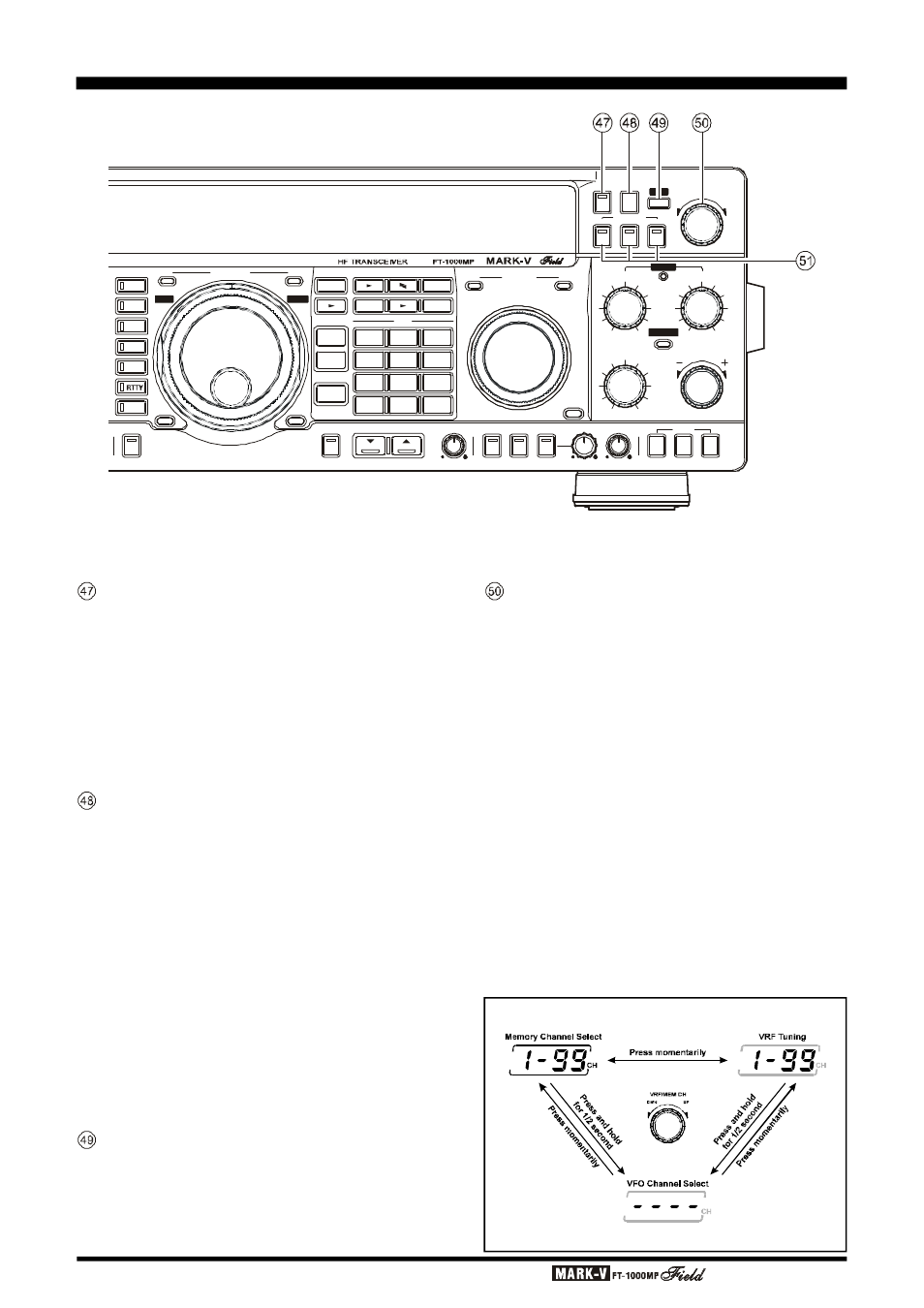
VRF/MEM CH Knob
When the VRF feature is engaged, use this
detended knob to tune the passband of the narrow in-
put preselector filter manually for maximum receiver
sensitivity (and out-of-band interference rejection).
At other times (when the VRF feature is “off”), this
knob selects the operating memory channel when the
memories are active (but not retuned). When the VFO
or memory tune functions of the main display are ac-
tive, turning this knob causes the Sub VFO display to
temporarily show the frequencies of the memories
(memory check), without otherwise affecting operation.
The channel number of the selected memory is dis-
played at all times at the center right of the display (in
front of “CH”).
Pressing and holding this knob for ½ second en-
ables the “VFO Step” feature, which allows
“channellizing” the VFO for quick frequency navigation.
Menu Selection 1-5 sets the VFO Channel step size.
F
RONT
P
ANEL
C
ONTROLS
VRF/MEM CH Knob Sequence
Note: VRF only functions on the 160-20 M Amateur Bands
R X
MAIN VFO-A
SUB VFO-B
R X
TX
NOTCH
TX
RCL
7
3
QMB
BAND
STO
DUAL
M A
A B
M CK
A M
M GRP
RPT
A B
VFO/
MEM
FAST
LOCK
LOCK
LSB
USB
CW
AM
FM
PKT
CLASS-A
AF REV
SPOT
BK-IN KEYER
SUB SQL
SPEED
TUNER
NOR
SHIFT
NOTCH
WIDTH
CLAR
NAR1
NAR2
BAND WIDTH
NB
VRF
VRF/MEM CH
PITCH
CLAR
CLEAR
RX
TX
1.8
1
1 0
4
2 1
7
SUB
DE
3.5
2
14
5
24.5
8
29
0
18
6
28
9
ENT
DOWN
U P
DWN
UP
IDBT
VRF
IDBT