Ccessory, Nstallation, Page 13 o – Vertex Standard FT-1000MP User Manual
Page 15: Caution - please read, Inear, Mplifier, Nterfacing, Bout
Page 13
O
PERATING
M
ANUAL
REMOTE
B
A
ANT
KEY
BACKUP
LIN
CAT
DVS-2
BAND DATA
+13.8V
TRV
TX GND
R X A N T
PACKET
RTTY
PTT
EXT
ALC
EXT
SPKR
PATCH
AF OUT
GND
OFF
OFF
IN
OUT
C W
SIDETONE
ON
ACC
ON
OUTPUT
DC 13.8V
2 0 0 m A
INPUT
DC 13.8V
20 A
INPUT
AC 100-120V ~
50-60Hz 6A
FUSE
T8A
DC IN
~ A C I N
E
E
RY
ALC
AC
FUSE
GND
RF IN
RF OUT
A
N
T
-
A
A
N
T
1
H
F
A
n
te
n
n
a
IN
P
U
T
1
E
X
T
A
L
C
T
X
G
N
D
G
N
D
G
N
D
~
A
C
I
N
OFF
LIN
ON
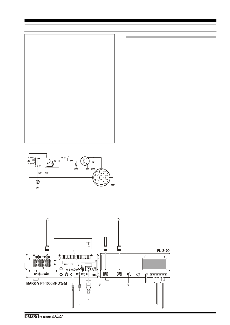
When using jack,
move switch to the "
" position
TX GND
LIN
ON
Caution - Please Read!!
The MARK-V FT-1000MP
Field is designed for use
with the FL-7000/VL-1000 when QSK operation
with a linear amplifier is desired. If you are using a
different amplifier, do not attempt QSK operation
with the linear if its switching circuitry requires that
the MARK-V FT-1000MP
Field’s relay be enabled.
Using pins 2 and 8 of the BAND DATA jack for
other amplifiers will not work unless the control line
signals are carefully matched, and damage may
result otherwise.
Your transceiver’s warranty does not cover dam-
age resulting from improper connections to this
jack, so if you are not sure of the linear amplifier’s
break-in capabilities or switching requirements, the
safest approach is to enable the relay, use the TX
GND jack (after setting the LIN switch to the “ON”
position) and resort to non-QSK operation. This will
help prevent possible damage to the amplifier or
transceiver.
L
INEAR
A
MPLIFIER
I
NTERFACING
A
BOUT
ALC
The MARK-V FT-1000MP
Field provides an exter-
nal ALC jack on the rear panel (RCA-type jack) for
input of Automatic Level Control voltage from a linear
amplifier.
ALC voltage is used to provide dynamic control of
the output of the transceiver, so as not to provide more
drive than is needed for full amplifier output. The ALC
control voltage range is 0 to –4 V DC, with the voltage
going more negative as the amplifier’s drive require-
ments are approaching fulfillment.
The MARK-V FT-1000MP
Field’s ALC system is
very typical of designs in the amateur radio industry,
and consequently is compatible with many manufac-
tured and home-built amplifiers. However, ALC volt-
age may be generated by an amplifier in a manner
incompatible with efficient ALC operation in the MARK-
V FT-1000MP
Field, and it is important that you recog-
nize the differences in amplifier ALC circuits before pro-
ceeding with ALC line connection.
r ALC circuits which detect Power Output from the
amplifier, and generate negative-going ALC control
voltage when maximum output power has been re-
alized, will generally work properly with the MARK-
V FT-1000MP
Field.
The exact amount of ALC voltage fed to the MARK-
V FT-1000MP
Field can usually be adjusted via a
potentiometer on the rear panel of the amplifier.
r ALC circuits which detect Amplifier Tube Grid Cur-
rent, and generate ALC voltage when excessive
grid current is present, may not work well with the
MARK-V FT-1000MP
Field and other similar trans-
ceivers, as the ALC voltage may be generated be-
cause of amplifier mis-tuning not related to an ex-
cessive-drive condition. With amplifiers deriving
their ALC voltage in this manner, we recommend
that you not connect the ALC line, and rather let the
amplifier’s protection circuitry manage its ALC re-
quirements internally.
A
CCESSORY
I
NSTALLATION
1
4
7
8
5
2
6
3
TX GND
BAND DATA
Jack
LIN Switch
OFF ON
Q1008
40V DC, 150 mA max.